Field electric power system decontamination cleaning tool

A technology for power devices and cleaning tools, which is applied to the field of decontamination and cleaning tools for power devices in the field, can solve the problems of falling into the eyes, small adjustable range of scrubbing angle, inhaling dust and the like

Inactive Publication Date: 2017-05-10
刘刚
View PDF0 Cites 2 Cited by
  • Summary
  • Abstract
  • Description
  • Claims
  • Application Information

AI Technical Summary

Problems solved by technology

Before the arrival of spring and autumn every year, rain and fog increase. In order to prevent flashover accidents caused by dirt and dust on power equipment, the porcelain parts (mainly insulators) of power equipment need to be dust-removed and cleaned, and then painted. Anti-fouling flash paint, this work requires a lot of manual work, and the staff wipes it bit by bit with a rag in their hands. The workload is very heavy and the intensity of fatigue is very high.
Moreover, it is inconvenient for the staff to stand and move when cleaning on the equipment, so they can only work with one hand, and the other hand must hold the porcelain column to ensure personal safety and prevent falling from high altitudes. If you can touch the equipment at close range, you will inhale a large amount of dust at the same time, which will also cause considerable damage to your health.
[0003] At present, there is a device on the market that uses the extension rod to lift the rag into the air to scrub the power system equipment, which can solve the problem of dust inhalation or contamination due to the traditional scrubbing method being too close to the power system equipment, and has a better protective effect. , to ensure the health of the operator, but this scrubbing equipment also has the following disadvantages: 1, because the rag is lifted into the air by the extension rod for scrubbing, the scrubbing strength of the rag is greatly reduced, resulting in unclean scrubbing; 2. 1. The operation method of using the extension rod to lift high into the air requires the operator to continuously control the movement of the rag at the high altitude on the ground, which is very time-consuming and laborious; 3. When scrubbing, it is necessary to raise the head and continuously observe the scrubbing process, so that the scrubbed solid particles may fall into the eyes , which seriously threatens the safety of the eyes; 4. When encountering stubborn stains, it needs to be wiped off with force and soaked in water, but it is difficult for the scrubbing equipment that lifts the extension rod to achieve such a function; 5. Since the operator is operating on the ground, the position and The length of the extension rod is fixed and other factors limit, the adjustable range of the scrubbing angle is very small, and it is easy to have a dead angle of scrubbing, and it is impossible to achieve thorough scrubbing; 6. The scrubbing equipment using the extension rod is generally only suitable for scrubbing at a height of less than ten meters. Scrubbing at a height of tens of meters cannot be completed at all, so there is a problem of limited scrubbing height; 7. During scrubbing, dirt and dust will fall to a part of other equipment, dirty other equipment, and adhere to a part of the rag , so it is necessary to scrub the equipment for a while, put the extension rod down, and then clean the rag again, which is very inefficient, and generally requires an auxiliary person who cleans the rag to cooperate with the operation

Method used


Image

  • Field electric power system decontamination cleaning tool
  • Field electric power system decontamination cleaning tool
  • Field electric power system decontamination cleaning tool

Examples


Embodiment Construction

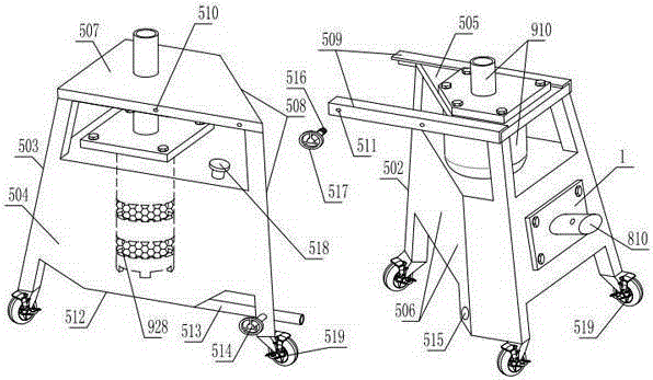
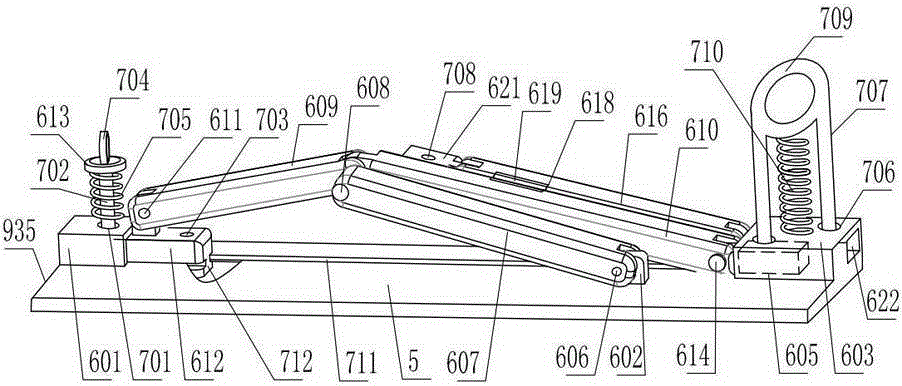
[0028] As shown in the figure, this field power device decontamination cleaning tool includes a cleaning head 3 driven by a power device 1 through a transmission hose 2. The cleaning head includes a vertically arranged rotating brush 4, and one side of the rotating brush is covered with a horizontal A protective cover 5 with a C-shaped cross-section, a handle 6 is fixed on the outside of the protective cover, and a horizontally extending upper rod 7 is fixed on the inner upper end of the protective cover. The end of the upper rod can only rotate with the upper end of the rotary brush through the upper connecting device. The lower end of the inner side of the cover is hinged with a lower rod 9 that can swing up and down through a horizontal shaft 8. The lower rod is rotatably matched with the lower end of the rotary brush through the lower connecting device, and the lower rod is also inserted and fitted with the lower end of the rotary brush through the lower connecting device. ...


PUM


Abstract

The invention discloses a field electric power system decontamination cleaning tool, which comprises a cleaning head driven by a power device through a transmission hose. The cleaning head comprises a vertically arranged rotary brush; a protective cover with a C-shaped cross section covers one side of the rotary brush; a handle is fixedly arranged on the outer side of the protective cover; an upper rod extending horizontally is fixedly arranged on the upper end of the inner side of the protective cover; the end part of the upper rod is in running fit to the upper end of the rotary brush through an upper connecting device; and a lower rod capable of swinging up and down is hinged to the lower end of the inner side of the protective cover through a horizontal shaft, and is in running fit to the lower end of the rotary brush through a lower connecting device. The field electric power system decontamination cleaning tool has the advantages that the structure is reasonable, a scrubbing task can be quickly completed according to the shape of a device to be scrubbed, two modes of close-distance scrubbing and long-distance scrubbing can be freely switched quickly without the need for changing the location of an operating personnel, a scrubbing angle can be adjusted at will, stubborn stains can be scrubbed without dead corners, the time and the labor can be saved, a scrubbing personnel can be well protected and cannot breath and be contaminated by dust, the problem that dirt enters eyes is avoided, the scrubbed dust dirt cannot fall onto the device below, the limitation of the scrubbing height is avoided, one person can independently complete the scrubbing task, and a scrubbing effect is high.

Description

technical field [0001] The invention relates to a decontamination and cleaning tool for an electric device in the field. Background technique [0002] At present, cleaning and decontamination of power equipment in the power system is a very heavy and repetitive work, and it also has certain harm to the health of the staff. Before the arrival of spring and autumn every year, rain and fog increase. In order to prevent flashover accidents caused by dirt and dust on power equipment, the porcelain parts (mainly insulators) of power equipment need to be dust-removed and cleaned, and then painted. Anti-fouling flashover coating, this work requires a lot of manual work, and the staff wipes it bit by bit with a rag in their hands. The workload is very heavy and the intensity of fatigue is very high. Moreover, it is inconvenient for the staff to stand and move when cleaning on the equipment, so they can only work with one hand, and the other hand must hold the porcelain column to ens...

Claims


Application Information

Patent Timeline
IPC IPC(8): B08B1/04B08B3/02B08B5/04B08B13/00B08B15/02
CPCB08B3/02B08B5/04B08B13/00B08B15/02B08B2203/0223B08B1/32B08B1/12
Inventor 刘刚
Owner 刘刚
Why Eureka
Try Eureka