Method for removing iron from raw materials and movable magnetic system iron removal device

A moving, magnetic system technology, applied in the field of magnetic separation, can solve the problems of prolonging the iron removal time, affecting the iron removal rate, and low work efficiency, so as to improve the quality of iron removal, improve the effect of iron removal, and improve the efficiency of iron removal Effect

Inactive Publication Date: 2017-05-10
李振信
View PDF8 Cites 0 Cited by
  • Summary
  • Abstract
  • Description
  • Claims
  • Application Information

AI Technical Summary

Problems solved by technology

Among them, when the automatic slurry iron removal machine removes iron, it needs to stop the feeding, and it needs to be fed again after the material is discharged to remove iron. Remove iron, and then use the rubber sleeve set on the magnetic rod to perform scraping type iron removal. This method will easily cause the surface of the magnetic rod to wear and affect its service life, and the actuator that drives the rubber sleeve to move contains equipment such as cylinders or oil cylinders. , complex structure, high failure rate; although the permanent magnetic cylinder magnetic separator can continuously remove iron, but because of its weak magnetism, the iron removal rate is affected, and the water consumption is large, the cylinder is easy to wear, and the maintenance cost is high; the vertical ring High gradient magnetic separator also has the problems of high cost, complicated structure and high maintenance cost
[0003] The above-mentioned iron remover can basically combine the iron absorption and iron transport steps into one, and complete it in one step, but the iron removal step needs to be operated separately with the help of other actuators, which not only has a complex structure, but also prolongs the iron removal time and reduces the overall iron removal. efficiency

Method used


Image

  • Method for removing iron from raw materials and movable magnetic system iron removal device
  • Method for removing iron from raw materials and movable magnetic system iron removal device
  • Method for removing iron from raw materials and movable magnetic system iron removal device

Examples


Embodiment Construction

[0031] The present invention will be further described in detail below in conjunction with the accompanying drawings and specific embodiments.

[0032] In the present invention, the height direction corresponding to the use state is defined as the vertical direction, the end far away from the ground is defined as the upper end, and the end close to the ground is defined as the lower end.

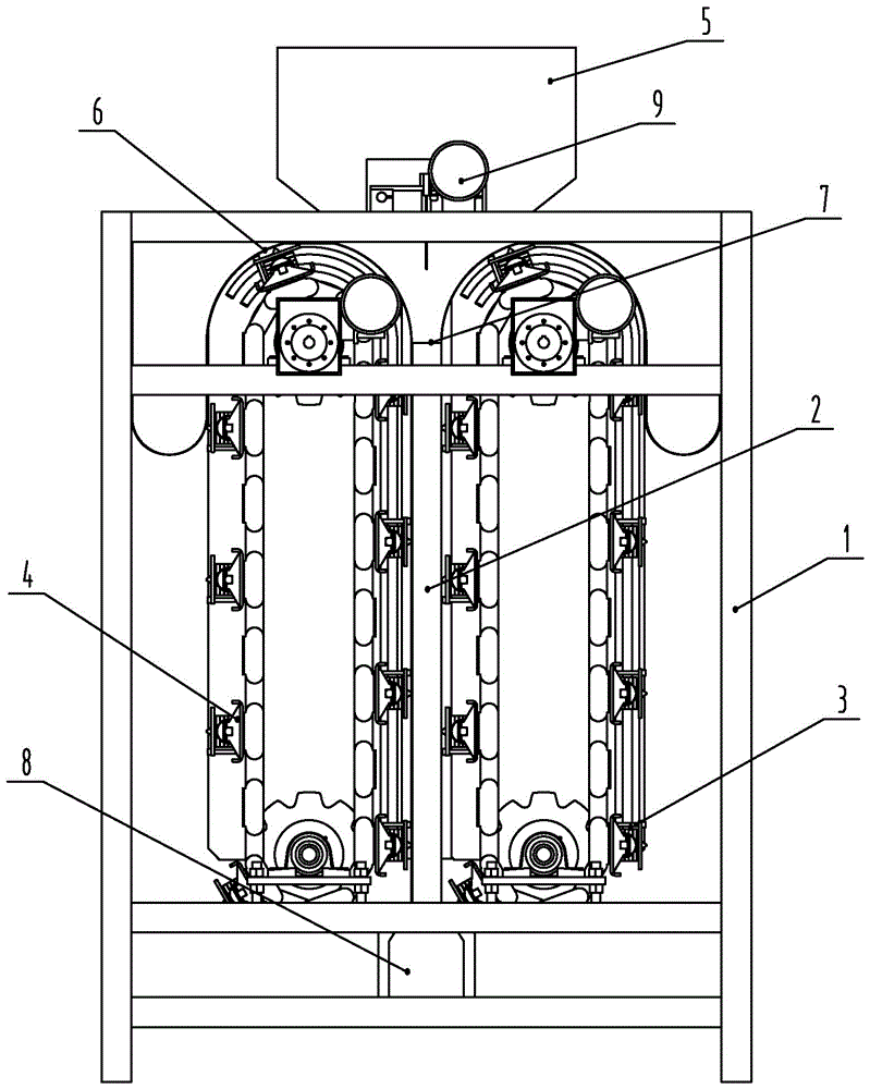
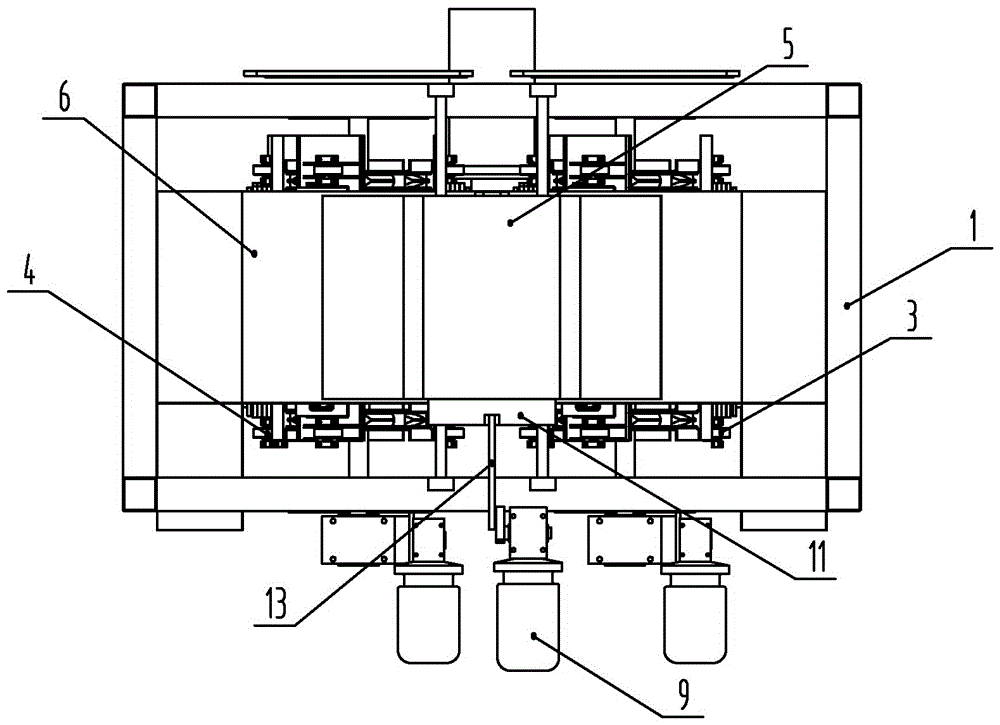
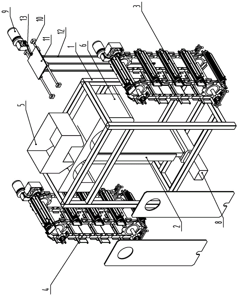
[0033] Such as figure 1 and figure 2 As shown, the present invention is equipped with a vertically arranged passing barrel 2 in the frame 1, and the cross section of the passing barrel 2 is a flat rectangle. The upper end of the feeding barrel 2 is a feed port 7, and the lower end is a discharge port 8, and a flared cloth bin 5 is arranged on the feed port 7. The first magnetic system 3 is set on one side of the barrel 2, and the second magnetic system 4 is set on the other side. The first magnetic system 3 and the second magnetic system 4 are placed along the long side of the rectangle a...


PUM


Abstract

The invention discloses a method for removing iron from raw materials and a movable magnetic system iron removal device, and belongs to the technical field of magnetic separation. The iron removal device comprises a frame, a material passing cylinder is mounted in the frame, one end of the material passing cylinder is provided with a feed port, and the other end of the material passing cylinder is provided with a discharge port. The iron removal device is characterized in that a turnover wall is connected at the feed port or the discharge port, a magnetic system is arranged on the outer side of the material passing cylinder and moves to the feed port from the discharge port, and a magnet in the magnetic system passes the turnover wall, then continues moving and is far away from the tail end of the turnover wall. The iron removal device fully automatically and continuously removes iron, the magnetic system can automatically and continuously absorb, transport and remove the iron under matching of the material passing cylinder and the turnover wall of the material passing cylinder, iron removal efficiency is improved, most iron stays at the feed port, firstly adsorbed and then transported, the magnetic system at the discharge port can adsorb less residual iron in the materials, iron removal quality is improved, the magnetic system moves in the whole process, and the structure of the device is greatly simplified.

Description

technical field [0001] The invention belongs to the technical field of magnetic separation, and in particular relates to a magnetic system moving type iron removal equipment. Background technique [0002] The current iron remover is divided into permanent magnet iron remover and electromagnetic iron remover according to the source of magnetic force, and permanent magnet iron remover is divided into permanent magnetic drum magnetic separator, strong magnetic stick magnetic separator, Suspended magnetic separator and fully automatic wet magnetic separator, etc. Electromagnetic iron remover is divided into electromagnetic dry powder iron remover, automatic slurry iron remover, vertical ring high gradient magnetic separator and suspended electromagnetic self-unloading iron remover machine etc. Among them, when the automatic slurry iron removal machine removes iron, it needs to stop the feeding, and it needs to be fed again after the material is discharged to remove iron. Remov...

Claims


Application Information

Patent Timeline
Patent Type & Authority Applications(China)
IPC IPC(8): B03C1/26
CPCB03C1/26
Inventor 李振信李圆
Owner 李振信
Why Eureka
Try Eureka