multifunctional power converter

A technology of power converter and power conversion, which is applied to output power conversion devices, instruments, and DC power input to DC power output. Effect of Improving Power Conversion Efficiency

Inactive Publication Date: 2018-11-13
产晶积体电路股份有限公司
View PDF6 Cites 0 Cited by
  • Summary
  • Abstract
  • Description
  • Claims
  • Application Information

AI Technical Summary

Problems solved by technology

[0006] However, the disadvantage of the above prior art is that the drive controller must separately receive the sensing signal from the primary coil and the current sensing signal from the reference coil, so that the drive controller needs to be configured with two independent signal pins, and the first branch The piezoresistor and the second voltage dividing resistor will occupy a considerable area, which affects the cost of the overall circuit layout, especially when it is realized in the form of an integrated circuit.

Method used


Image

  • multifunctional power converter
  • multifunctional power converter
  • multifunctional power converter

Examples


Embodiment Construction

[0082] The implementation of the present invention will be described in more detail below with reference to the drawings and reference numerals, so that those skilled in the art can implement it after studying this specification.

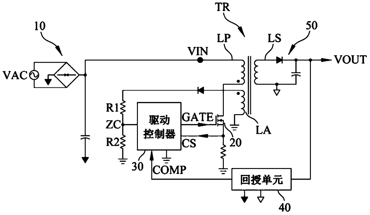
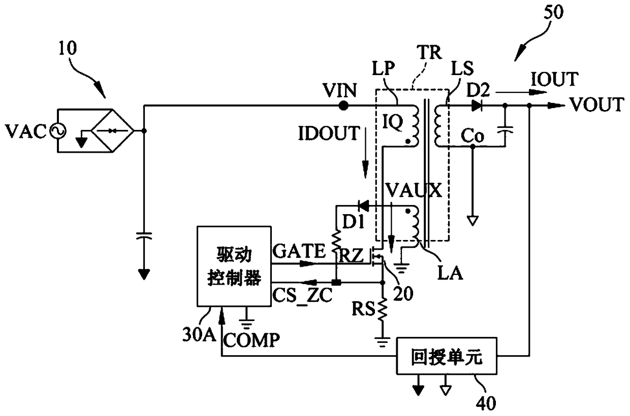
[0083] refer to figure 2 , a schematic diagram of the multifunctional power converter according to the first embodiment of the present invention. Such as figure 2 As shown, the multifunctional power converter of the first embodiment of the present invention is essentially a secondary measurement feedback mechanism, and includes an input filter unit 10, a transformer TR, a switching transistor 20, a drive controller 30A, a feedback unit 40, The output unit 50 is used to provide the power conversion function of dynamic detection, wherein the transformer TR mainly includes a primary side coil LP, a reference coil LA and a secondary side coil LS, and the switching transistor 20 can be realized by a metal oxide semiconductor (MOS) power transistor, I...


PUM


Abstract

The present invention relates to a multi-function power converter comprising an input filter unit, a voltage transformer, a switching transistor, a drive controller, a feedback unit and an output unit. A power supply converting function with dynamic detecting can be provided. A sensing signal from a primary coil and a sensing signal from a reference coil are combined into a current sensing zero detection signal so that a digital control unit determines whether a secondary current is discharged to zero and detects a bottom position and a bottom number to decide whether to turn on the switching transistor. Meanwhile, when the switching transistor is turned on, current sensing is performed to determine whether to turn off the switching transistor. Accordingly, the multifunctional power converter of the invention can greatly reduce switching loss and raise the power supply converting efficiency. In particular, the digital control unit is used; practical needs can be satisfied by means of updating firmware programs; and high elasticity is realized.

Description

technical field [0001] The present invention relates to a multifunctional power converter, in particular, the sensing signal from the primary side coil and the sensing signal from the reference coil are combined into a current sensing zero point detection signal, and received by a single signal pin to The digital control unit can judge whether the secondary side current is discharged to zero according to the current sensing zero point detection signal, and detect the valley bottom position and the number of valley bottoms, so as to decide whether to turn on the switching transistor and reduce the switching loss. At the same time, when the switching transistor is turned on , for current sensing to decide whether to turn off the switching transistor. Background technique [0002] Different electronic products require power supplies of different voltages or currents to operate. For example, integrated circuits (ICs) require 5V or 3V, electric motors require 12V DC, and lamp tub...

Claims


Application Information

Patent Timeline
Patent Type & Authority Patents(China)
IPC IPC(8): H02M7/217H02M3/335
Inventor 林树嘉林敬渊林志峰
Owner 产晶积体电路股份有限公司
Why Eureka
Try Eureka