
Method for computing voltage sensitivity of automatic voltage control system

A voltage sensitivity and control system technology, applied in the direction of AC network voltage adjustment, reactive power compensation, etc., can solve the problems of affecting the speed and accuracy of regulation, the actual value of the power grid is very different, and cannot accurately represent the actual value, etc. Yield, the effect of improving speed and accuracy

Active Publication Date: 2017-04-26
LEADZONE SMART GRID TECH
View PDF2 Cites 1 Cited by
  • Summary
  • Abstract
  • Description
  • Claims
  • Application Information

AI Technical Summary

Problems solved by technology

However, the voltage sensitivity is dynamically changed according to the real-time status of the bus. The voltage sensitivity calculated by dividing the reactive power change detected by the traditional period of time by the voltage change represents the value of the past period of time, which cannot be accurately calculated. Indicates the actual value in a period of time in the future, so using it in the upcoming actual regulation in the future will inevitably affect the speed and accuracy of regulation
[0004] In addition, the collected real-time voltage and reactive power values ​​used to calculate the voltage sensitivity occasionally have a large difference from the actual value of the power grid due to various reasons. Using these problematic data to calculate the voltage sensitivity will definitely cause errors
No matter how good the calculation method is, it cannot guarantee that the calculated voltage sensitivity is completely correct. Therefore, considering the safety of the power grid and the generator set, the initial calculation results must be verified.

Method used


Image

  • Method for computing voltage sensitivity of automatic voltage control system
  • Method for computing voltage sensitivity of automatic voltage control system

Examples


Embodiment Construction

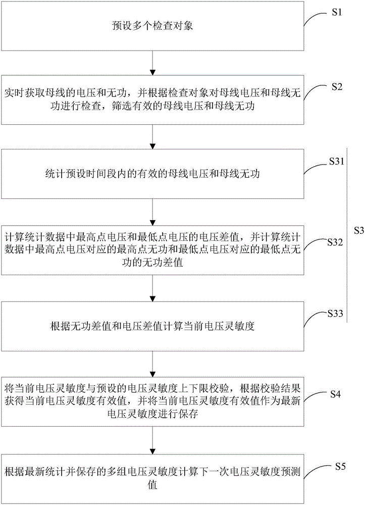
[0026] refer to figure 1 , a method for calculating the voltage sensitivity of an automatic voltage control system proposed by the present invention includes the following steps.

[0027] S1. Presetting multiple inspection objects. The multiple inspection objects include one or more of validity inspection, fluctuation inspection, double measurement deviation inspection, double busbar deviation inspection and blocking limit inspection.

[0028] In this embodiment, the validity check is to compare the current value with the set data valid range, and if it exceeds the valid range, it is unqualified. The volatility check is to compare the current value with the last historical value, and if the difference exceeds the set fluctuation threshold, it is unqualified. Double measurement deviation check is to compare the data of two measurement points of the same data, if the difference is greater than the set deviation threshold, it is unqualified. The double-bus deviation inspection...


PUM


Abstract

The invention discloses a method for computing the voltage sensitivity of an automatic voltage control system. The method, by setting examination items, screens the acquired data, strictly examines data used during the computing, is conducive to guaranteeing the quality of the acquired data, effectively prevents bad data from influencing the result of the computing, and increases the precision in computing current voltage sensitivity. According to the invention, when computing the prediction value of the voltage sensitivity, the method uses an algorithm similar to weighted average, by collecting statistics from historical record of voltage sensitivity and the changing trend of numerical values, to compute the actual voltage sensitivity which best conforms to next adjustment, such that the computed prediction value of the voltage sensitivity more conforms to the changing trend of a power grid within a short time period in the future, can effectively increase the speed and precision of actual adjustment of the automatic voltage control system and also increases the percent of pass of the adjustment.

Description

technical field [0001] The invention relates to the technical field of automatic voltage control (AVC) of a power plant, in particular to a calculation method for voltage sensitivity of an automatic voltage control system. Background technique [0002] After the automatic voltage control system receives the voltage command issued by the dispatching master station, it needs to convert the difference between the voltage target and the current voltage value into a reactive power difference, which involves the voltage sensitivity concerned by this patent, that is, every The reactive power variation corresponding to the unit voltage variation. [0003] At present, the similar products of most manufacturers do not pay enough attention to the calculation of voltage sensitivity, and most of them use the traditional method of dividing the reactive power change detected within a period of time by the voltage change. However, the voltage sensitivity is dynamically changed according to...

Claims


Application Information

Patent Timeline
IPC IPC(8): H02J3/12H02J3/16
CPCH02J3/12H02J3/16Y02E40/30
Inventor 王统义殷骏程琦
Owner LEADZONE SMART GRID TECH
Learn More