Hydraulic frame assembly equipment used for door and window profile assembly
A door and window profile and hydraulic technology, which is applied in the field of hydraulic framing equipment for assembling door and window profiles of core-shell structure, can solve problems such as deviation of joints, easy damage of profile ends, uneven force application, etc.
- Summary
- Abstract
- Description
- Claims
- Application Information
AI Technical Summary
Problems solved by technology
Method used
Image

Examples
specific Embodiment approach 1
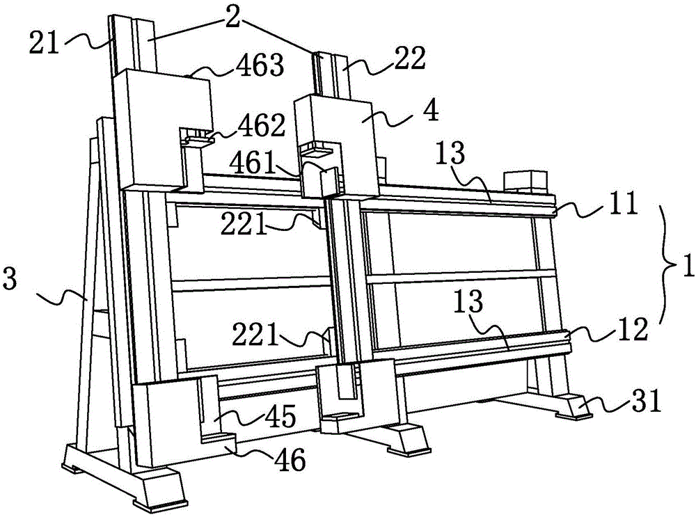
[0024] Specific Embodiment 1: Combining figure 1 Describe the present embodiment. The hydraulic framing equipment used for the assembly of core-shell structure door and window profiles described in this embodiment has a set of transverse parallel bars 1 and a set of longitudinal parallel bars 2 in a perpendicular relationship thereto. The transverse The parallel rod 1 is fixed on the support foot 31, and the support foot 31 is arranged in parallel to form a rigid support 3. The horizontal parallel rod 1 is divided into an upper rod 11 and a lower rod 12, and the longitudinal parallel rod 2 is divided into a solid rod 21 and a moving rod 22, the fixed rod 21 is located at one end of the horizontal parallel rod 1 and its relative position with the horizontal parallel rod 1 is fixed, and both the upper rod 11 and the lower rod 12 have hydraulic transmission slides Rail 13, the moving rod 22 has a plurality of transmission sliders 221, the plurality of transmission sliders 221 are...
specific Embodiment approach 2
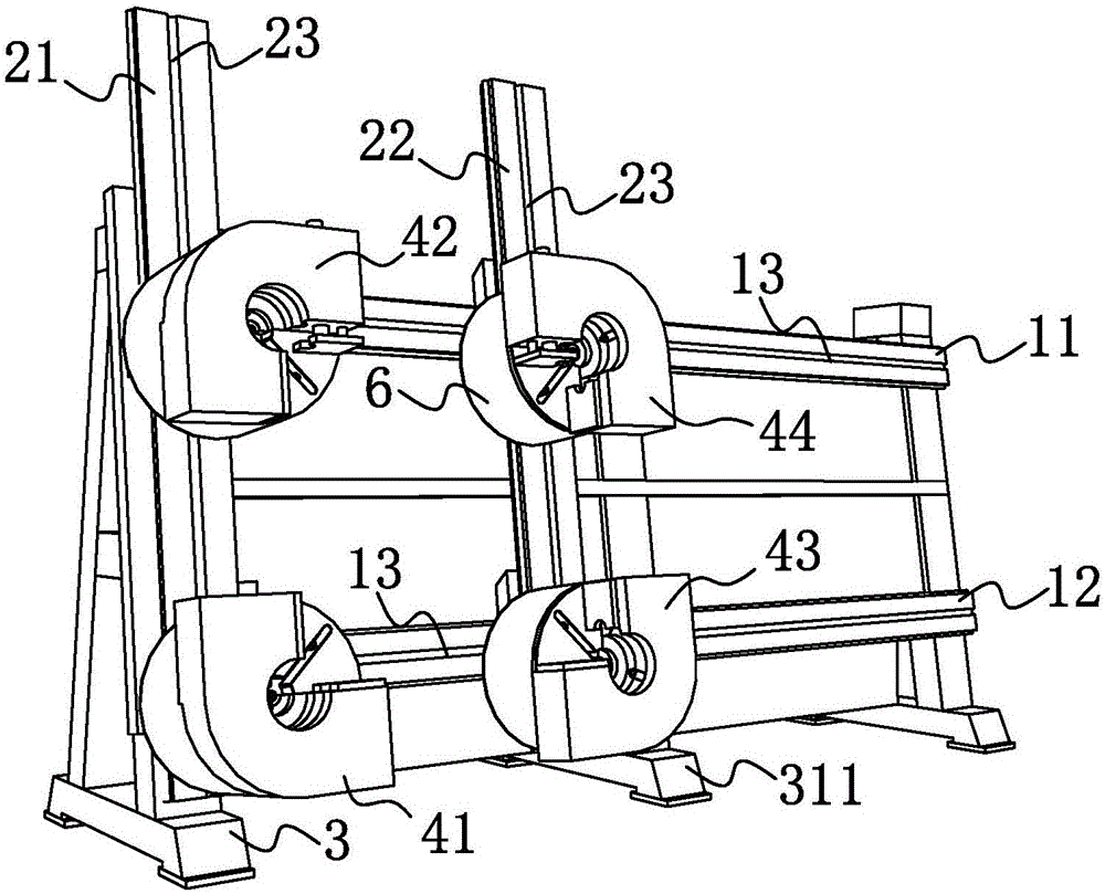
[0026] Specific Embodiment 2: Combining figure 2 , image 3 and Figure 4 Describe this embodiment, the hydraulic framing equipment used for the assembly of core-shell structure door and window profiles described in this embodiment, the corner end workbench 4 set on the solid rod 21 is divided into the second fixed at the bottom of the solid rod 21 One 41 and the second table 42 that are movably arranged on the solid rod 21, the corner end workbench 4 set on the movable rod 22 is divided into the third table 43 that is fixed on the bottom end of the movable rod 22 and the third table 43 that is movably arranged on the movable rod 22 The fourth platform 44 on 22; the longitudinal parallel bar 2 has a longitudinal hydraulic guide rail 23, and the second platform 42 and the fourth platform 44 are respectively connected with the longitudinal hydraulic guide rail 23, and on the longitudinal hydraulic guide rail 23 Under the action, it moves along the longitudinal parallel bar 2 ...
specific Embodiment approach 3
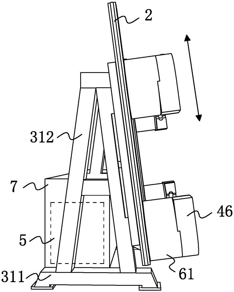
[0028] Embodiment 3: Combining figure 2 , image 3 and Figure 4 Describe this embodiment, the hydraulic frame assembly equipment used for the assembly of core-shell structure door and window profiles described in this embodiment, the L-shaped box body 46 also has a pneumatic shaft 463, and the pneumatic shaft 463 is electrically connected to the control center 5 connected, the pneumatic shaft 463 is respectively connected with the pressure application vertical plate 461 or the pressure application horizontal plate 462, after the control center 5 issues a pressure application command to the pneumatic shaft 463, the pressure application vertical plate 461 or the pressure-applying horizontal plate 462 pressurizes the door and window profiles under the control of the pneumatic shaft 463 to realize the assembly of the door and window profiles; the others are the same as the specific embodiment 1 or 2.
[0029] The technical effect of this embodiment is: the pneumatic shaft is u...
PUM
| Property | Measurement | Unit |
|---|---|---|
| Radian | aaaaa | aaaaa |
Abstract
Description
Claims
Application Information
 - R&D
- Intellectual Property
- Life Sciences
- Materials
- Tech Scout
- Unparalleled Data Quality
- Higher Quality Content
- 60% Fewer Hallucinations
Browse by: Latest US Patents, China's latest patents, Technical Efficacy Thesaurus, Application Domain, Technology Topic, Popular Technical Reports.
© 2025 PatSnap. All rights reserved.Legal|Privacy policy|Modern Slavery Act Transparency Statement|Sitemap|About US| Contact US: help@patsnap.com