
Hidden multi-column type hydraulic lifting garbage transferring box

A garbage transfer box and hydraulic lifting technology, which is applied to garbage cans, garbage collection, household appliances, etc., can solve problems such as manufacturing troubles, garbage floating in the box, and garbage flying all over the sky

Inactive Publication Date: 2017-04-26
张煌辉
View PDF1 Cites 11 Cited by
  • Summary
  • Abstract
  • Description
  • Claims
  • Application Information

AI Technical Summary

Problems solved by technology

[0002] In order to ensure urban sanitation, trash cans will be set up on both sides of the roads in the city. The existing trash cans are usually placed directly on the ground. As a result, garbage is flying all over the sky, and sanitation workers are also more laborious when recycling the garbage in the garbage can
Therefore someone has applied for Chinese patent 201310221716.X, and the title of the patent is "a kind of underground dustbin", which includes a dustbin body, a dustbin cover, and a hydraulic lifting device. The hydraulic lifting device includes a fuel tank, a fuel tank cover, an oil cylinder, a chain, Support arms, fixed brackets, lifting brackets and lifting rollers, the hydraulic lifting device is located on one side of the garbage box body, the garbage box cover is above the garbage box body, and the garbage box body is located below the ground. The hydraulic lifting device lifts the garbage bin and the garbage cover at the same time and puts them on the transport vehicle for transportation. The disadvantages of this structure are: 1. The hydraulic lifting device is a unilateral structure and requires chains, supporting arms, fixed brackets, lifting brackets and The transmission structure such as lifting rollers is complex in structure and troublesome to manufacture, and the unilateral structure is not easy to hold up a large-sized garbage bin, and the stability of the lifting action is poor; 2. The garbage bin cover and the garbage bin body are assembled together. The sanitation workers have to put the garbage bin cover and the garbage bin body together on the sanitation vehicle, and when dumping the garbage, they also need to open the garbage bin cover, which is troublesome to operate; 3. Since the garbage bin is set below the ground, in case of typhoon, heavy rain, etc. In disastrous weather, rainwater will easily flood the garbage bin, causing damage to electrical equipment, floating garbage in the box, and polluting the environment; 4. There is only a small opening on the lid of the garbage bin. Since the garbage is a solid material, the garbage put into the small opening can only be piled up. In the lower part, it will not flow to the surrounding area by itself, forming a conical shape, which is easy to block the input port, while the surrounding area is very empty, so that the garbage in the box is unevenly distributed after accumulation, resulting in a small amount of garbage box capacity; 5. Because the garbage box is closed state, after the garbage is put into the box, it is easy to rot and breed bacteria, which will cause the box to stink, produce germs, and pollute the environment

Method used


Image

  • Hidden multi-column type hydraulic lifting garbage transferring box
  • Hidden multi-column type hydraulic lifting garbage transferring box
  • Hidden multi-column type hydraulic lifting garbage transferring box

Examples


Embodiment Construction

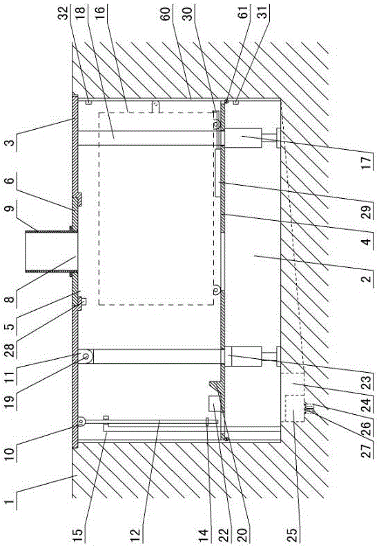
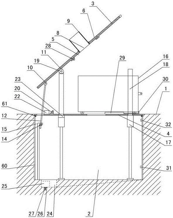
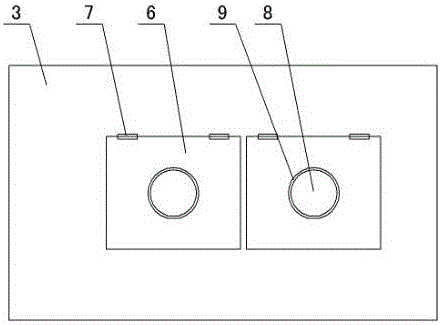
[0011] The invention relates to a hidden multi-column hydraulic lifting garbage transfer box, such as figure 1 — Figure 4As shown, it is characterized in that: there is a pit 2 in the ground 1, a bracket 63 is arranged at the bottom of the pit, an upper cover 3 and a lower platform 4 are arranged in the pit, the upper cover is flat with the ground 1, and in the upper cover There is an oversized garbage input port 5, and a large input port cover 6 is arranged in the oversized garbage input port. Garbage input port 8, dustbin 9 is set on the small piece of garbage input port, the first movable fulcrum 10 and the second movable fulcrum 11 are set under the loam cake 3, the first movable fulcrum is connected with a pull rod 12, and an adjusting nut 14 is set on the pull rod. A limit pull hook 15 is set in the pit, the pull rod passes through the limit pull hook, and the adjustment nut on the pull rod is in contact with the limit pull hook. A dustbin 16 and an ozone generator 22 ...


PUM


Abstract

A hidden multi-column type hydraulic lifting garbage transferring box is characterized in that a pit is formed in the ground; a support is arranged at the bottom of the pit; an upper cover and a lower platform are arranged in the pit; a large garbage throw-in port is formed in the upper cover and is internally provided with a large throw-in port cover; the front side or the rear side of the large throw-in port cover is connected with the upper cover in an overturning manner through a hinge; a small garbage throw-in port is formed in the large throw-in port cover and is provided with a garbage barrel; a first movable supporting point and a second movable supporting point are arranged below the upper cover; the lower portion of the first movable supporting point is connected with a pull rod which is provided with an adjusting nut; a limiting pull hook is arranged in the pit; the lower platform is provided with a garbage can and an ozone generator; a hydraulic lifting mechanism is arranged below the lower platform and comprises four or more fixing sleeves; an oil cylinder is arranged in each fixing sleeve; each oil cylinder piston rod makes contact with the pit; oil cylinder bodies penetrate the lower platform; the left side oil cylinder is matched with the second movable supporting point of the upper cover through a pin; a waste material induction head is arranged below the upper cover; the lower platform is provided with a pushing oil cylinder which is fixed to the garbage can through a pull pin; a stopping block is manufactured on the lower platform; and a water level induction head is arranged on the inner wall, located below the lower platform, in the pit.

Description

technical field [0001] The invention relates to a garbage bin, in particular to a concealed multi-column hydraulic lifting garbage transfer box. Background technique [0002] In order to ensure urban sanitation, trash cans will be set up on both sides of the roads in the city. The existing trash cans are usually placed directly on the ground. As a result, garbage is flying all over the sky, and sanitation workers are also more laborious when recycling the garbage in the garbage can. Therefore someone has applied for Chinese patent 201310221716.X, and the title of the patent is "a kind of underground dustbin", which includes a dustbin body, a dustbin cover, and a hydraulic lifting device. The hydraulic lifting device includes a fuel tank, a fuel tank cover, an oil cylinder, a chain, Support arms, fixed brackets, lifting brackets and lifting rollers, the hydraulic lifting device is located on one side of the garbage box body, the garbage box cover is above the garbage box bod...

Claims


Application Information

Patent Timeline
IPC IPC(8): B65F1/14B65F1/16
CPCB65F1/1447B65F1/16B65F2001/1653B65F2210/129B65F2210/132B65F2210/168B65F2210/176
Inventor 张煌辉
Owner 张煌辉
Learn More