
Blood collecting tube automatic falling and conveying device

A technology for blood collection tubes and delivery tubes, which is applied in the field of progressive tube devices for blood collection tubes, can solve the problems of long operation time, stuck blood collection tubes, complicated structures, etc., and achieves the effects of simple assembly, easy processing and low cost.

Inactive Publication Date: 2017-04-26
合肥妙思智能医疗科技有限公司
View PDF10 Cites 5 Cited by
  • Summary
  • Abstract
  • Description
  • Claims
  • Application Information

AI Technical Summary

Problems solved by technology

[0006] In the above technical solution, it is necessary to set a fixing plate between the support plate and the clamping transmission plate to prevent the blood collection tube from disturbing, and to set a plurality of fixing positions matching the shape of the blood collection tube on the fixing plate for fixing the blood collection tube, Prevent it from moving around, otherwise it is easy to cause the blood collection tube to get stuck, so the operation time is long, the structure is more complicated, and the efficiency is also low, and further improvement is needed

Method used


Image

  • Blood collecting tube automatic falling and conveying device
  • Blood collecting tube automatic falling and conveying device
  • Blood collecting tube automatic falling and conveying device

Examples


Embodiment 1

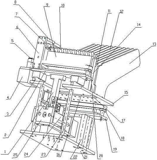
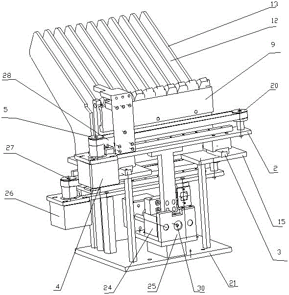
[0065] See Figure 1 to Figure 8 , An automatic tube dropping and conveying tube device for blood collection tubes, including a control system, a support plate 15 is connected to the bottom plate 21 through a first column 23, a tube taking device is arranged on the supporting plate 15, and the tube taking device includes a fixed on the supporting plate 15 There are several take-out tube sheets 13 at one end, and a clamping groove 12 for holding the blood collection tube is formed between every two take-up tube sheets 13. In this embodiment, there are 11 tube-taking sheets 13 and the two adjacent tube-taking sheets There are a total of 10 clamping grooves 12 formed between 13 and the number of rows is the same as that of the currently commercially available packaged blood collection tubes; in actual use, the tube sheet 13 can be directly fixed on the support plate 15; or several The film fetching tube 13 is first manufactured to form an assembly, and then fixed on the support pl...

Embodiment 2

[0112] The structure and principle of this embodiment are basically the same as those of the first embodiment, and the differences are:

[0113] The angle between the bearing surface 11 and the vertical direction is greater than the angle between the vertical direction on the tube-taking sheet 13 and the blood collection tube can slide downward more conveniently.

[0114] In this embodiment, the first motor, the second motor, and the third motor all adopt servo motors, and the control accuracy is higher.


PUM


Abstract

The invention discloses a blood collecting tube automatic falling and conveying device. The device comprises a baseplate, a support plate, and a tube taking device arranged on the support plate; the tube taking device includes multiple tube taking pieces fixed at one end of the support plate; clamping grooves for clamping blood collecting tubes are formed between every two tube taking pieces; a tube pushing device is arranged at the other end of the support plate; a blood collecting tube keeping device is arranged between the tube pushing device and the tube taking pieces; a vertical through hole is formed in the support plate between the blood collecting tube keeping device and the tube taking pieces; and a blood collecting tube conveying device is arranged at the lower part of the support plate. The blood collecting tube automatic falling and conveying device integrates the tube taking device with the tube falling and conveying device as a whole, realizes automation of taking, falling and conveying of the blood collecting tubes, greatly improves the blood collecting efficiency, is small in size, short in conveying distance, flexible and convenient to use and high in working efficiency, provides more convenience for subsequent transfer, distribution, marking and management work of the blood collecting tubes, and relieves the complex work of operators.

Description

Technical field [0001] The present invention relates to the technical field of medical devices, in particular to an advance tube device for blood collection tubes. Background technique [0002] Blood testing is a conventional method for medical diagnosis of diseases. Vacuum blood collection tubes are the most common way to collect blood as laboratory samples. Vacuum blood collection tubes are already a necessary and mass-used medical device in hospitals, with an annual consumption of more than 6 billion The massive application of vacuum blood collection tubes makes the blood collection method more reliable, and also provides great convenience for the blood collection work of medical staff. However, in order to cope with multiple patients, it is necessary to paste labels with patient information, inspection items, etc. on the test tubes, which makes a large number of blood collection tubes need to be transferred, distributed, identified, and managed during use, which becomes a com...

Claims


Application Information

Patent Timeline
IPC IPC(8): B65C9/02
CPCB65C9/02
Inventor 张元宏李进华郑刚
Owner 合肥妙思智能医疗科技有限公司
Learn More