
A method of manufacturing a large-diameter steel pipe socket joint

A manufacturing method and large-diameter technology, applied in the direction of pipes/pipe joints/fittings, manufacturing tools, forming tools, etc., can solve the problems of high manufacturing cost, large diameter expansion and forming force of socket head upset forging, complicated manufacturing process, etc., and achieve the goal of manufacturing Low cost, small investment in spinning forming equipment, and simple manufacturing process

Active Publication Date: 2019-04-16
上海佳方钢管集团太仓有限公司
View PDF11 Cites 0 Cited by
  • Summary
  • Abstract
  • Description
  • Claims
  • Application Information

AI Technical Summary

Problems solved by technology

This forming method has the disadvantages of large diameter expansion forming force, complex manufacturing process, and high manufacturing cost of the socket head.

Method used


Image

  • A method of manufacturing a large-diameter steel pipe socket joint
  • A method of manufacturing a large-diameter steel pipe socket joint
  • A method of manufacturing a large-diameter steel pipe socket joint

Examples


Embodiment 1

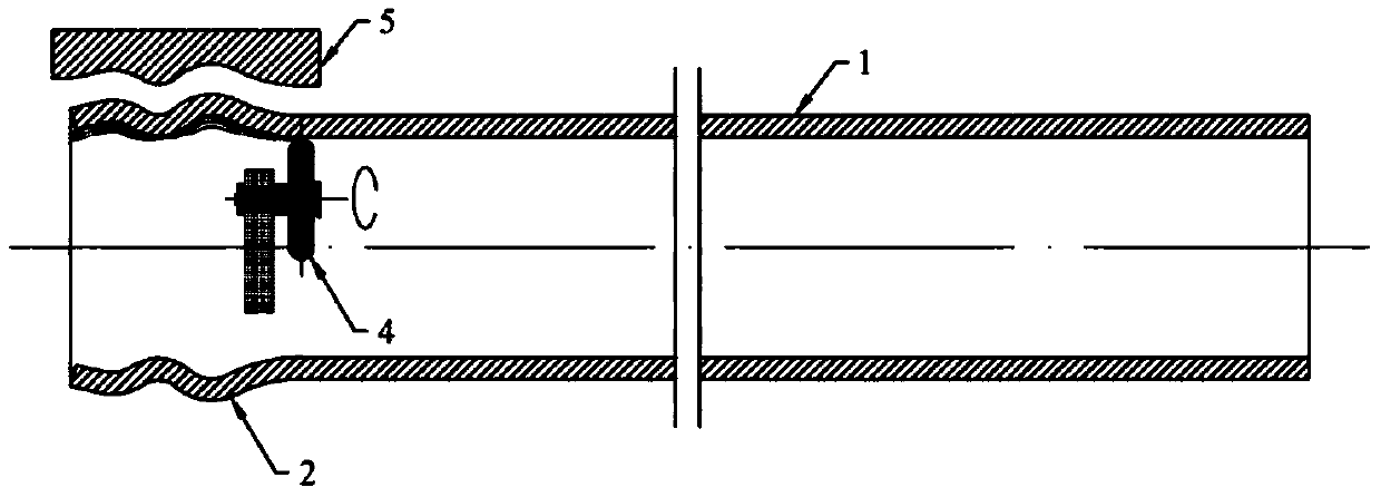
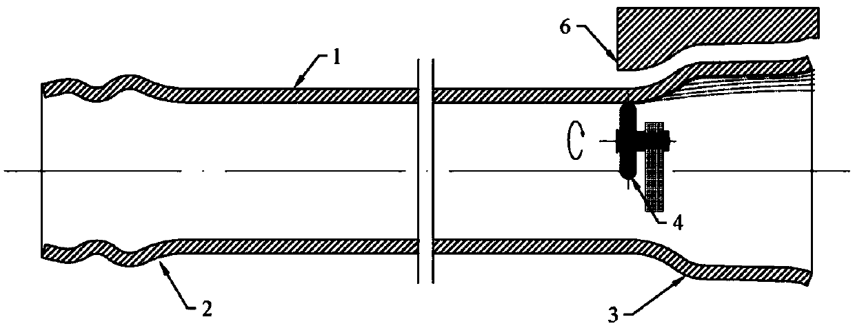
[0034] A method for manufacturing a large-diameter steel pipe socket joint, such as Figure 1-2 As shown, the two ends of the steel pipe 1 are respectively exerted force by the rotary wheel 4, so that the local continuous plastic deformation occurs, and the plug 2 and the socket 3 are formed respectively.

Embodiment 2

[0036] A method for manufacturing a large-diameter steel pipe socket joint, comprising the following steps:

[0037] 1) The two ends of the processed steel pipe 1 are heated by an intermediate frequency induction coil, and the heating temperature is 600-1100° C.;

[0038] 2) if figure 1 As shown, use the rotary wheel 4 to perform multi-pass spinning on the heating end to form the plug 2;

[0039] 3) if figure 2 As shown, the rotary wheel 4 is used to perform multi-pass spinning forming on the other heated end to form the socket head 3 .

[0040] Table 1: Yield strength and tensile strength of the steel pipe before spinning and the plug and socket after spinning in Example 2

[0041]

Embodiment 3

[0043] A method for manufacturing a large-diameter steel pipe socket joint, comprising the following steps:

[0044] 1) Clamping of the steel pipe: install the steel pipe 1 on the spinning machine, and position and fix it through the positioning device and the fixture;

[0045] 2) Spinning forming of the joint: using an intermediate frequency induction coil to heat the end of the steel pipe 1 at a heating temperature of 600-1100°C; then, if figure 1 As shown, the rotary wheel 4 moves along a predetermined trajectory, and exerts force on the end of the heated steel pipe 1, causing it to undergo local continuous plastic deformation. After multi-pass spinning, it is molded to the plug mold 5 to achieve a predetermined shape and Dimensions required to form plug 2;

[0046] 3) Spinning forming of the socket head: heating the other end of the steel pipe 1 with an intermediate frequency induction coil at a heating temperature of 600-1100°C; then, if figure 2 As shown, the rotary w...


PUM


Abstract

The invention discloses a manufacturing method of a large-diameter steel tube socket and spigot joint. Acting force is applied to the two ends of a steel tube through a spinning roller correspondingly, so that the two ends of the steel tube are partially subjected to plastic deformation to form a socket and a spigot. The manufacturing method of the large-diameter steel tube socket and spigot joint is simple, reasonable and easy to implement. The manufacturing process is stable and reliable. The large-diameter steel tube socket and spigot joint is suitable for volume production. The ends of the steel tube are subjected to direct spinning forming without welding. A sealing ring mounting position can be arranged on the spigot to facilitate mounting and fixing of a sealing ring. Moreover, spinning forming force is small, spinning forming equipment investment is small, and the production and maintenance cost is low.

Description

technical field [0001] The invention belongs to the technical field of steel pipes, and in particular relates to a method for manufacturing a large-diameter steel pipe joint, in particular to a method for manufacturing a large-diameter steel pipe socket joint. Background technique [0002] At present, the interface forms of steel pipes are mainly threaded connections, welded connections and socket connections. Among them, the threaded connection is only suitable for small-diameter steel pipes; the welded connection is suitable for medium and large-diameter steel pipes, but on-site manual welding joints have high labor intensity, low construction efficiency, high technical requirements for workers, and the quality of welds is directly affected by environmental factors, etc. Disadvantages: Socket connection is that the two ends of the steel pipe are respectively formed with a socket and a plug, and the plug of one steel pipe is inserted into the socket of the other steel pipe ...

Claims


Application Information

Patent Timeline
Patent Type & Authority Patents(China)
IPC IPC(8): B21C37/28B21D22/16B21D37/16F16L25/10
CPCB21C37/28B21D22/16B21D37/16F16L25/10
Inventor 顾永发
Owner 上海佳方钢管集团太仓有限公司
Learn More