Manufacturing method of large-diameter steel tube socket and spigot joint
A manufacturing method and large-diameter technology, applied in the direction of pipes/pipe joints/fittings, manufacturing tools, forming tools, etc., can solve the problems of high manufacturing cost, complex manufacturing process, and large forming force of socket upsetting and diameter expansion. Low cost, simple manufacturing process, and small investment in spinning forming equipment
- Summary
- Abstract
- Description
- Claims
- Application Information
AI Technical Summary
Problems solved by technology
Method used
Image

Examples
Embodiment 1
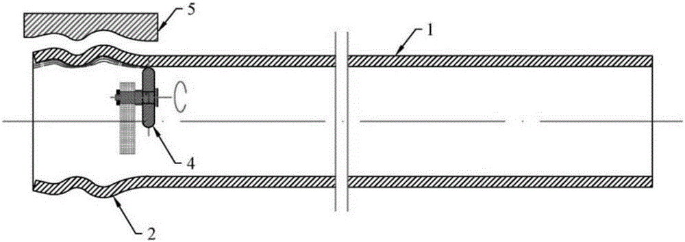
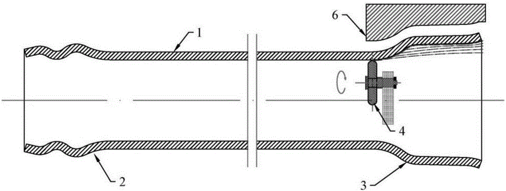
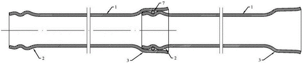
[0034] A method for manufacturing a large-diameter steel pipe socket joint, such as Figure 1-2 As shown, the two ends of the steel pipe 1 are respectively exerted force by the rotary wheel 4, so that the local continuous plastic deformation occurs, and the plug 2 and the socket 3 are formed respectively.
Embodiment 2
[0036] A method for manufacturing a large-diameter steel pipe socket joint, comprising the following steps:
[0037] 1) The two ends of the processed steel pipe 1 are heated by an intermediate frequency induction coil, and the heating temperature is 600-1100° C.;
[0038] 2) if figure 1 As shown, use the rotary wheel 4 to perform multi-pass spinning on the heating end to form the plug 2;
[0039] 3) if figure 2 As shown, the rotary wheel 4 is used to perform multi-pass spinning forming on the other heated end to form the socket head 3 .
[0040] Table 1: Yield strength and tensile strength of the steel pipe before spinning and the plug and socket after spinning in Example 2
[0041] Steel pipe before forming Spin plug Spinning head Yield strength (MPa) 235 255 265 Tensile strength (MPa) 375 395 405
Embodiment 3
[0043] A method for manufacturing a large-diameter steel pipe socket joint, comprising the following steps:
[0044] 1) Clamping of the steel pipe: install the steel pipe 1 on the spinning machine, and position and fix it through the positioning device and the fixture;
[0045] 2) Spinning forming of the joint: using an intermediate frequency induction coil to heat the end of the steel pipe 1 at a heating temperature of 600-1100°C; then, if figure 1 As shown, the rotary wheel 4 moves along a predetermined trajectory, and exerts force on the end of the heated steel pipe 1, causing it to undergo local continuous plastic deformation. After multi-pass spinning, it is molded to the plug mold 5 to achieve a predetermined shape and Dimensions required to form plug 2;
[0046] 3) Spinning forming of the socket head: heating the other end of the steel pipe 1 with an intermediate frequency induction coil at a heating temperature of 600-1100°C; then, if figure 2 As shown, the rotary w...
PUM
 Abstract
Description
Claims
Application Information
 - R&D
- Intellectual Property
- Life Sciences
- Materials
- Tech Scout
- Unparalleled Data Quality
- Higher Quality Content
- 60% Fewer Hallucinations
Browse by: Latest US Patents, China's latest patents, Technical Efficacy Thesaurus, Application Domain, Technology Topic, Popular Technical Reports.
© 2025 PatSnap. All rights reserved.Legal|Privacy policy|Modern Slavery Act Transparency Statement|Sitemap|About US| Contact US: help@patsnap.com