An active card communication system and method based on working clock calibration

A working clock and clock calibration technology, which is applied to the record carrier used by the machine, the instrument, the induction record carrier, etc., can solve the problems of large service life gap, large clock deviation, product maintenance, upgrade, recycling, etc., and achieve improvement The communication success rate and the effect of improving the service life

Active Publication Date: 2019-06-28
WUHAN RUINAJIE ELECTRONICS TECH
View PDF4 Cites 0 Cited by
  • Summary
  • Abstract
  • Description
  • Claims
  • Application Information

AI Technical Summary

Problems solved by technology

At present, most RFID active card clocks use an internal RC oscillator, which is affected by the accuracy of the RC oscillator and the error caused by the battery supply voltage, resulting in inaccurate timing of the internal sleep timer and a large clock deviation (generally within ± 20%), with the accumulation of timing counts, the clock deviation will become larger and larger, especially when the active card communicates with the card reading device, due to the clock deviation, the timing of the active card and the timing of the card reading device cannot Synchronization, and then can not communicate, at this time the active card will be considered to have reached the end of life
It can be seen that the same batch of active cards with the same specifications has a large gap in service life, and it is difficult to meet the demand for high life. When there is a large deviation in the dormancy time of the card, some products of the same batch will end their life prematurely, causing great changes to product maintenance, upgrades, and recycling.

Method used


Image

  • An active card communication system and method based on working clock calibration
  • An active card communication system and method based on working clock calibration

Examples


Embodiment Construction

[0018] The present invention will be described in more detail below in conjunction with the accompanying drawings and embodiments.

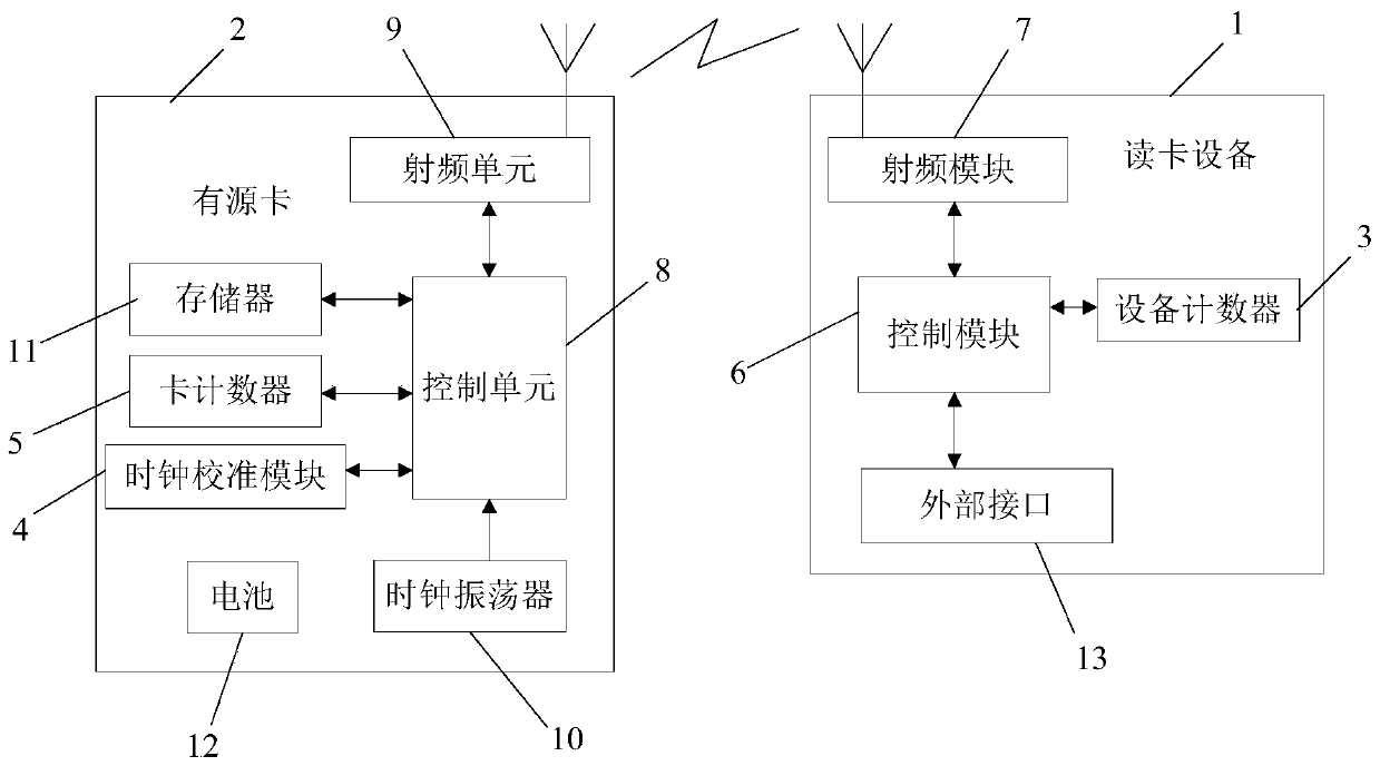
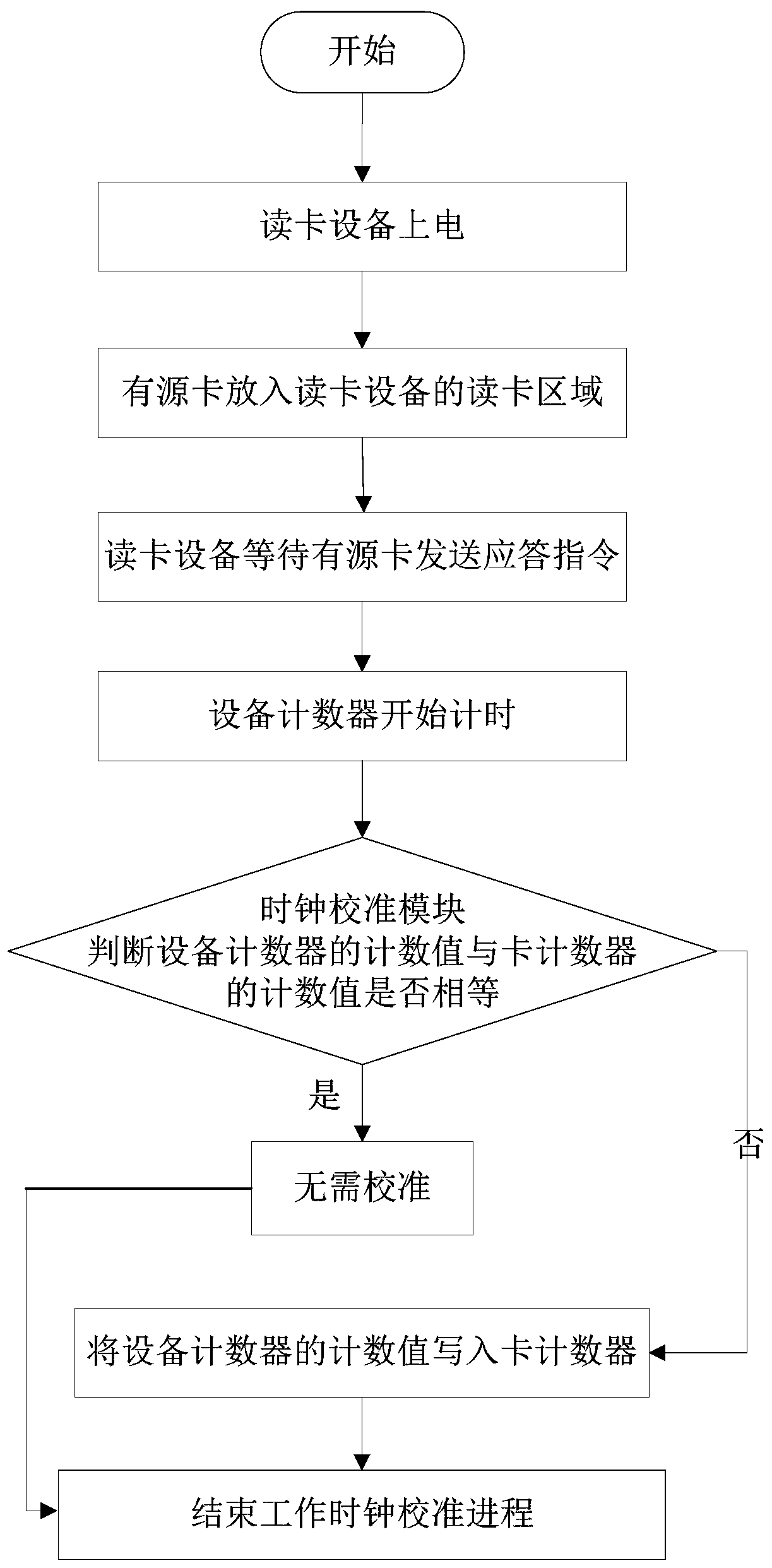
[0019] The invention discloses an active card communication system based on working clock calibration, such as figure 1 As shown, it includes a card reading device 1 and an active card 2, and the two establish communication in a wireless manner, the card reading device 1 has a built-in device counter 3, and the active card 2 has a built-in clock calibration module 4 and Card counter 5, the clock calibration module 4 is used to determine whether the count value of the device counter 3 is equal to the count value of the card counter 5 after the card reader device 1 and the active card 2 establish communication:

[0020] If they are equal, the working clock calibration process is ended;

[0021] If they are not equal, the count value of the device counter 3 is written into the card counter 5, so that the working clocks of the card reading device 1 ...


PUM


Abstract

The invention discloses an active card communication system and method based on working clock calibration. The active card communication system comprises card reading equipment and an active card, wherein the card reading equipment and the active card establish communication wirelessly. An equipment counter is arranged inside the card reading equipment in a built-in mode. A clock calibration module and a card counter are arranged in the active card in a built-in manner. The clock calibration module is used for determining whether a counting value of the equipment counter is equal to a counting value of the card counter after communication establishment between the card reading equipment and the active card; if so, a work clock calibration course is completed; and if not, the counting value of the equipment counter is written into the card counter and thus working clocks of the card reading equipment and the active card are synchronized and then the working clock calibration course is completed. Therefore, the communication success rate can be improved; the service life of the active card can be prolonged; and the active card can be maintained, upgraded, and recycled conveniently.

Description

technical field [0001] The invention relates to an active card communication system, in particular to an active card communication system and method based on working clock calibration. Background technique [0002] The active card is a wireless device powered by a battery. Its important technical requirement is low power consumption. In order to improve the service life, a sleep timer will be set in the active card to control the work and sleep of the active card through timing, so that Reduce power consumption. At present, most RFID active card clocks use an internal RC oscillator, which is affected by the accuracy of the RC oscillator and the error caused by the battery supply voltage, resulting in inaccurate timing of the internal sleep timer and a large clock deviation (generally within ± 20%), with the accumulation of timing counts, the clock deviation will become larger and larger, especially when the active card communicates with the card reading device, due to the c...

Claims


Application Information

Patent Timeline
Patent Type & Authority Patents(China)
IPC IPC(8): G06K7/10G06K19/077
CPCG06K7/10009G06K19/07749
Inventor 刘路路龚明扬叶玉成李宏杰张明宇
Owner WUHAN RUINAJIE ELECTRONICS TECH
Why Eureka
Try Eureka