
Missile rudder surface control mechanism

A control mechanism and rudder surface technology, applied to self-propelled bombs, projectiles, offensive equipment, etc., to achieve the effect of improving space efficiency and reducing occupancy

Active Publication Date: 2017-04-19
ZHEJIANG SCI-TECH UNIV
View PDF6 Cites 1 Cited by
  • Summary
  • Abstract
  • Description
  • Claims
  • Application Information

AI Technical Summary

Problems solved by technology

[0003] The purpose of the present invention is to provide a control mechanism for missile rudder surface, which can effectively save installation space under the premise of maintaining the existing aerodynamic shape of the missile body, and further Effectively reduce the occupancy of the volume of the projectile by the placement of the steering gear

Method used


Image

  • Missile rudder surface control mechanism
  • Missile rudder surface control mechanism
  • Missile rudder surface control mechanism

Examples


Embodiment Construction

[0019] The present invention will be further described below in conjunction with the accompanying drawings and embodiments.

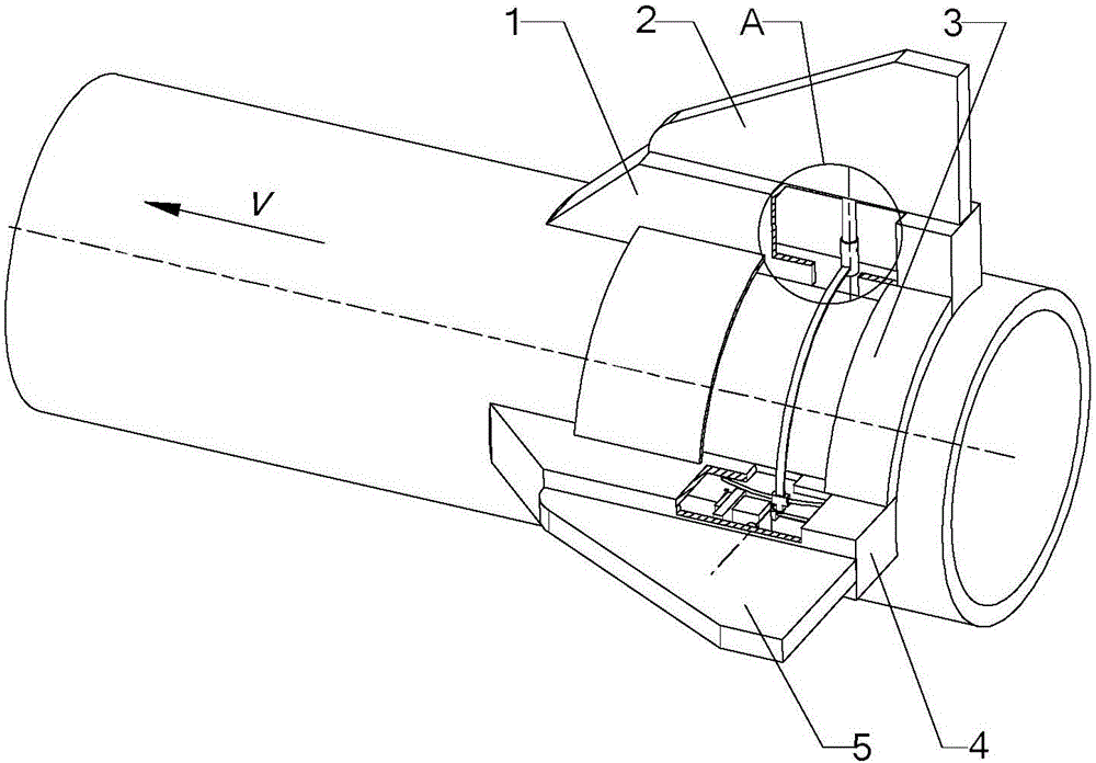
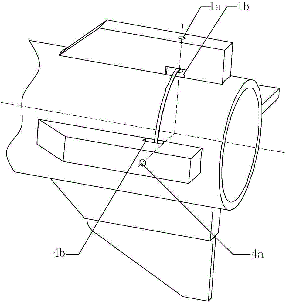
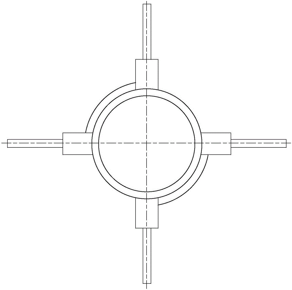
[0020] Such as Figure 1 to Figure 6 As shown, a missile rudder surface control mechanism includes a rudder cabin 1 and a rudder cabin 2 4; two rudder cabins 1 and two rudder cabins 4 are evenly distributed on the tail of the missile body along the circumference, and are fixed with the missile body Connection; two connecting cabins 3 are fastened to the body tail, and the two ends of each connecting cabin 3 are respectively fixedly connected with a rudder cabin 1 and a rudder cabin 2 4; 4 is connected with two rudders 5; each rudder one 2 is connected with a corresponding rudder cabin two 4 by a connecting rod one 6. figure 1 Among them, V is the running speed of the projectile.

[0021] Such as Figure 4 and 5 As shown, the rudder shaft-2a fixed on the rudder-2 passes through the bushing 6d fixed at one end of the connecting rod-6, and forms a revo...


PUM


Abstract

The invention discloses a missile rudder surface control mechanism. Much space of a missile body needs to be occupied for installation of rudder motors at present. According to the missile rudder surface control mechanism disclosed by the invention, each rudder room I is fixed to one adjacent rudder room II through a connection room; each rudder room I is connected with a rudder I, and each rudder room II is connected with a rudder II; each rudder I is connected with the corresponding rudder room II through a connection rod I; a rudder shaft I fixed on each rudder I penetrates through a shaft sleeve fixed to one end of the corresponding connection rod I, and forms a revolute pair with a through hole I and a blind hole of the corresponding rudder room I; each shaft sleeve is arranged in a through groove I of the corresponding rudder room I; a slide block fixed to the other end of each connection rod I forms a spherical pair with an annular guide rail, and the annular guide rail is fixed to the bottom of a through groove II of the corresponding rudder room II; a rudder motor I drives the corresponding slide block; and a rudder shaft II of each rudder II forms a revolute pair with a through hole II of the corresponding rudder room II, and a rudder motor II drives the corresponding rudder shaft II. According to the missile rudder surface control mechanism disclosed by the invention, the rudder motor of one special rudder is moved into the rudder room where the rudder motor of another rudder is located, thus occupation for the volume of the missile body is reduced, and the space utilization efficiency is effectively increased.

Description

technical field [0001] The invention belongs to the field of weapon equipment, and in particular relates to a control mechanism for a missile rudder surface. Background technique [0002] The missile rudder rotates around the rudder axis during flight to adjust the missile's position and posture and generate control force and control torque on the missile, so that the missile can adjust its flight trajectory in time to achieve the purpose of precise strike. At present, the rotation of most rudder surfaces is mainly controlled by the steering gear, and the steering gear is installed in the body of the projectile, which occupies a large volume of the projectile body. During design, the size of the projectile body must be increased to ensure the installation space of the steering gear and other related mechanisms. With the continuous development of missile technology, higher requirements are put forward for the external dimensions of missiles, and even special requirements are ...

Claims


Application Information

Patent Timeline
Patent Type & Authority Applications(China)
IPC IPC(8): F42B15/01
CPCF42B15/01
Inventor 胡明陈超陈文华宋浩马善红王文斌周煦武
Owner ZHEJIANG SCI-TECH UNIV
Learn More