A rapid dehumidification device for textile fabrics
A fast technology for textile fabrics, applied in the directions of drying gas arrangement, drying solid materials, progressive dryers, etc., can solve the problem of not improving the drying efficiency of the drying device, and achieve the effect of high body efficiency and improved drying efficiency.
- Summary
- Abstract
- Description
- Claims
- Application Information
AI Technical Summary
Problems solved by technology
Method used
Image

Examples
Embodiment 1
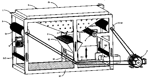
[0031] like figure 1 As shown, the present embodiment provides a textile cloth rapid dehumidification device comprising:
[0032] Box 1; and
[0033] Vibration moisture absorption mechanism 2, the vibration moisture absorption mechanism 2 is arranged on the right side of the box body 1, including the vibration component 21 and the moisture absorption component 22, the vibration component 21 drives the moisture absorption component 22 to reciprocate up and down to absorb moisture;
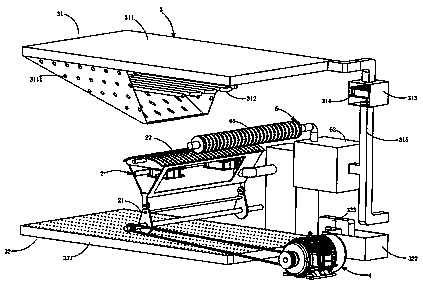
[0034] A drying mechanism 3, the drying mechanism 3 includes a heating air supply assembly 31 and an air outlet dust collection assembly 32, the heating air supply assembly 31 and the air outlet dust collection assembly 32 are respectively arranged on the upper and lower parts of the box body 1;
[0035] The driving mechanism 4 is connected to the oscillating assembly 21 to drive the oscillating assembly 21 to rotate.
[0036] In this embodiment, the oscillating moisture-absorbing mechanism 2 uses...
Embodiment 2
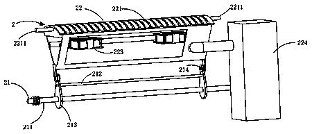
[0062] like image 3 As shown, as a preferred embodiment, the oscillating component 21 includes at least one oscillating unit, and the oscillating unit includes:
[0063] A camshaft 211, the two ends of the camshaft 211 are fixed on the box body 1, and one end thereof is connected to the driving mechanism 4 by means of belt transmission; and
[0064] A cam synchronous shaft 212, the cam synchronous shaft is arranged parallel to the cam shaft 211;
[0065] A cam 213, one end of the cam 213 is fixedly connected in series by the camshaft 211, and the other end is connected in series by the cam synchronous shaft 212;
[0066] The roller 214 , the roller 214 is rollingly arranged on the cam 213 , and the roller 214 is always rollingly matched with the edge of the cam 213 .
[0067] It should be noted that the embodiment of the vibration unit is not limited thereto, and the vibration unit can be added or deleted according to the specification parameters of the textiles to which th...
Embodiment 3
[0069] like Figure 4 As shown, as an improved technical solution, the drum dust suction mechanism 6 includes:
[0070] Dust suction roller 61, the dust suction roller 61 is located between the moisture absorption box 221 and the output cloth roller 521, the front and rear ends of which are rollingly arranged on the box body 1, and a number of dust suction holes are evenly distributed on it; and
[0071] A filter box 62 , one end of the filter box 62 communicates with the dust suction drum 61 through the air return pipe 63 , and the other end communicates with the heating air supply assembly 31 .
[0072] It should be noted that the filter box is connected with the heating and blowing mechanism 31 through the air inlet pipe 315, the dust-absorbing roller 61 absorbs the impurities on the textile and the impurities in the box body 1, and the absorbed impurities are mixed with air and enter the filter box 62, the air passes through the filter element 623, the impurities are filt...
PUM
 Abstract
Description
Claims
Application Information
 - R&D
- Intellectual Property
- Life Sciences
- Materials
- Tech Scout
- Unparalleled Data Quality
- Higher Quality Content
- 60% Fewer Hallucinations
Browse by: Latest US Patents, China's latest patents, Technical Efficacy Thesaurus, Application Domain, Technology Topic, Popular Technical Reports.
© 2025 PatSnap. All rights reserved.Legal|Privacy policy|Modern Slavery Act Transparency Statement|Sitemap|About US| Contact US: help@patsnap.com