An Optimum Structure for Adjusting the Movement of the Cutting Die

A technology of mobile adjustment and optimized structure, which is applied in the direction of metal processing, etc., can solve the problems of large upper and lower tolerances, inability to fit tightly, and large contact area of ​​the moving knife part of the knife die, and achieve reduced contact area, tight fit, and quick disassembly and assembly of tools Effect

Active Publication Date: 2018-04-27
李福全
View PDF6 Cites 0 Cited by
  • Summary
  • Abstract
  • Description
  • Claims
  • Application Information

AI Technical Summary

Problems solved by technology

The pressure plate, knife liner and blade are fixed on the fixed knife part and the moving knife part by screws to form a main body; at present, the fixed knife part of the knife mold is adjusted left and right on the drum, because the inner diameter of the fixed knife part of the knife mold and the outer diameter of the drum have a large contact area, It is time-consuming and labor-intensive to adjust the fixed knife part of the knife mold left and right on the drum. When the movable knife part is adjusted up and down on the drum, the internal teeth of the movable knife part of the knife mold cannot be closely matched with the gears on the drum.
The phenomenon that the upper and lower tolerances of the moving knife part of the knife mold are large on the roller; Bulk packaging, resulting in time-consuming and labor-intensive phenomena when disassembling and assembling the blades

Method used


Image

  • An Optimum Structure for Adjusting the Movement of the Cutting Die
  • An Optimum Structure for Adjusting the Movement of the Cutting Die
  • An Optimum Structure for Adjusting the Movement of the Cutting Die

Examples


Embodiment 1

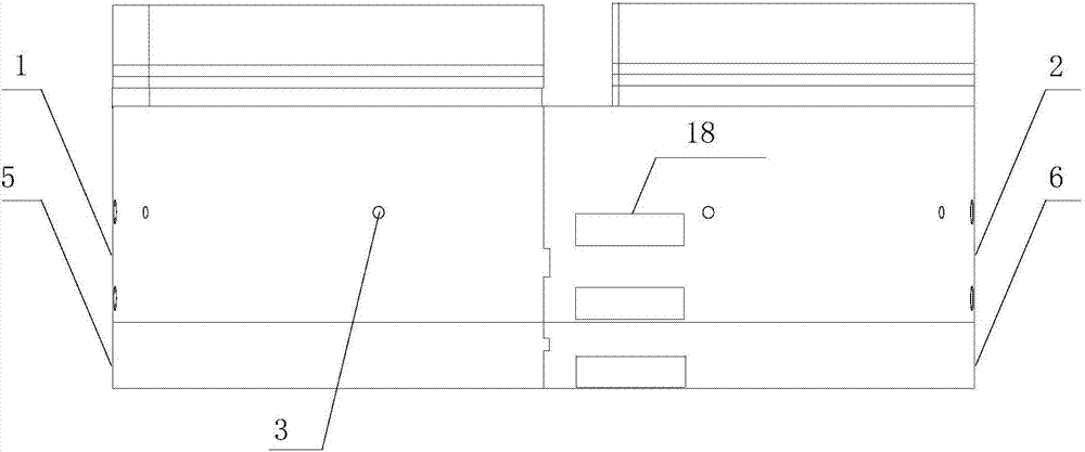
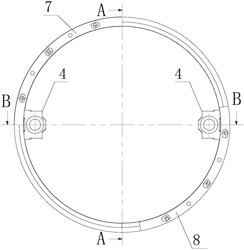
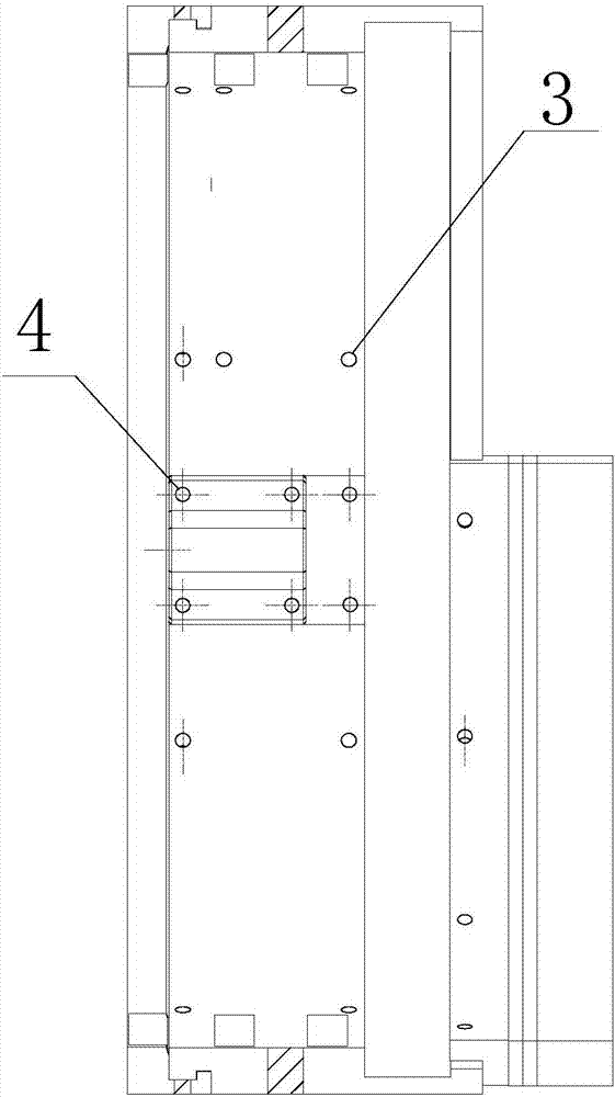
[0037] see Figure 1-14 , an optimized structure for adjusting the movement of the knife mold, including a knife mold main body, the knife mold main body is composed of a fixed knife main body, and the fixed knife main body is composed of a first fixed knife main body 1 and a second fixed knife main body 2 which are symmetrically arranged. The fixed knife main body 1 and the second fixed knife main body 2 are connected to each other to form a ring structure. The first fixed knife main body 1 and the second fixed knife main body 2 are provided with several steel ball embedding holes 3 that cooperate with steel balls. The first fixed knife main body 1 and the inner side of the second fixed knife body 2 are provided with a linear sliding unit slider 4, and the bottoms of the first fixed knife body 1 and the second fixed knife main body 2 are respectively installed with the first knife mold fixing ring 5 and the second knife mold fixed ring 5. Circle 6, the top of the first fixed ...

Embodiment 2

[0048] see Figure 15-21 , as another implementation of the present invention, the two ends of the grooved linear optical axis 22 are installed on the drum 41 through the linear optical axis fixing seat 42, and the middle part of the linear optical axis fixing seat 42 is provided with the grooved linear optical axis 22 The matching optical axis hole, the two sides of the optical axis hole are provided with fixing holes, the linear optical axis fixing seat 42 is fixed on the roller 41, the grooved linear optical axis 22 passes through the optical axis hole, and the grooved linear optical axis 22 is located on the linear optical axis The outer part of the shaft fixing seat 42 is sequentially covered with a thrust bearing 43, an adjusting hexagonal sleeve 44 and a round nut 45, wherein the inner circumference of the adjusting hexagonal sleeve 44 is provided with a protrusion matching the groove of the groove linear optical axis 22, the protrusion Snap into the groove of the groov...


PUM


Abstract

The invention discloses an optimized structure for movement and adjustment of a knife mold. The optimized structure for movement and adjustment of the knife mold comprises a knife mold main body. The knife mold main body is composed of a fixed knife main body. The fixed knife main body is composed of a first fixed knife body and a second fixed knife body which are arranged symmetrically. The first fixed knife body and the second fixed knife body are connected to form a ring structure. The first fixed knife body and the second fixed knife body are provided with a plurality of steel ball inlay holes matched with steel balls. The inner side of the first fixed knife body and the inner side of the second fixed knife body are each provided with a linear sliding unit sliding block. The top of the first fixed knife body and the top of the second fixed knife body are provided with a moving knife part and a fixed knife part correspondingly. The moving knife part is composed of a moving knife upper knife set, a moving knife base plate, a moving knife liner and a moving knife pressing plate. The bottom of the moving knife upper knife set is connected with a spline part on the inner circumference of the first fixed knife body. Through the optimized structure for movement and adjustment of the knife mold, the fixed knife part of the knife mold can slide easily on a roller; the fixed knife part is tight, and knives are fast in demounting and mounting; and the optimized structure is worth being popularized energetically.

Description

technical field [0001] The invention relates to a cutting die, in particular to an optimized structure for adjusting the movement of the cutting die. Background technique [0002] The current knife mold consists of a fixed knife part, a moving knife part and a blade. Installed on the roller, through the cooperation of the gear on the fixed knife part of the knife mold and the rack on the roller, the left and right adjustments can be made on the fixed knife part roller. The internal teeth of the moving knife part of the knife mold cooperate with the hexagonal bar gear on the roller to adjust the moving knife part up and down on the roller. The pressure plate, knife liner and blade are fixed on the fixed knife part and the moving knife part by screws to form a main body; at present, the fixed knife part of the knife mold is adjusted left and right on the drum, because the inner diameter of the fixed knife part of the knife mold and the outer diameter of the drum have a large ...

Claims


Application Information

Patent Timeline
Patent Type & Authority Patents(China)
IPC IPC(8): B26D7/26
CPCB26D7/2628
Inventor 李福全
Owner 李福全
Why Eureka
Try Eureka