
Method and system for determining partial discharge source position

A determination method and technology of partial discharge source, applied in the field of determination method and system of partial discharge source position

Active Publication Date: 2017-04-05
CHINA ELECTRIC POWER RES INST +2
View PDF9 Cites 7 Cited by
  • Summary
  • Abstract
  • Description
  • Claims
  • Application Information

AI Technical Summary

Problems solved by technology

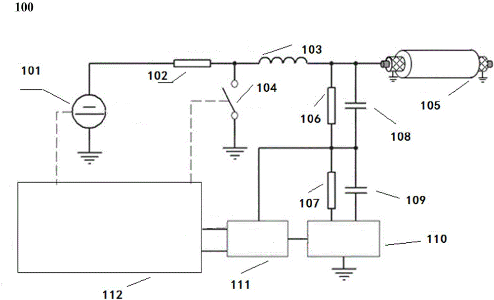
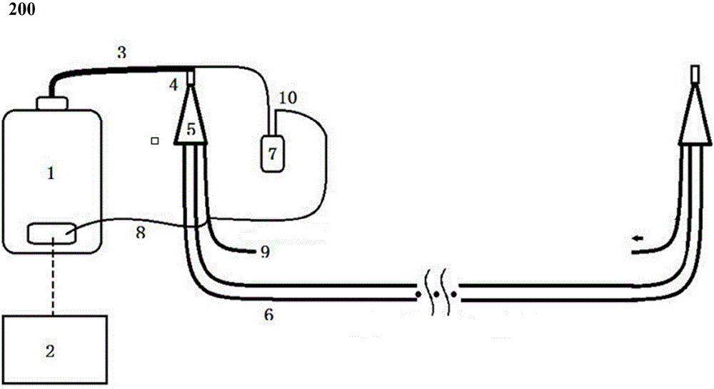
[0004] The present invention provides a method and system for determining the position of a partial discharge source, which is used to solve the problem of judging the position of a partial discharge source at the head / end of a cable line

Method used


Image

  • Method and system for determining partial discharge source position
  • Method and system for determining partial discharge source position
  • Method and system for determining partial discharge source position

Examples


Embodiment Construction

[0039] Exemplary embodiments of the present invention will now be described with reference to the drawings; however, the present invention may be embodied in many different forms and are not limited to the embodiments described herein, which are provided for the purpose of exhaustively and completely disclosing the present invention. invention and fully convey the scope of the invention to those skilled in the art. The terms used in the exemplary embodiments shown in the drawings do not limit the present invention. In the figures, the same units / elements are given the same reference numerals.

[0040] Unless otherwise specified, the terms (including scientific and technical terms) used herein have the commonly understood meanings to those skilled in the art. In addition, it can be understood that terms defined by commonly used dictionaries should be understood to have consistent meanings in the context of their related fields, and should not be understood as idealized or over...


PUM

PropertyMeasurementUnit
Lengthaaaaaaaaaa
Lengthaaaaaaaaaa

Abstract

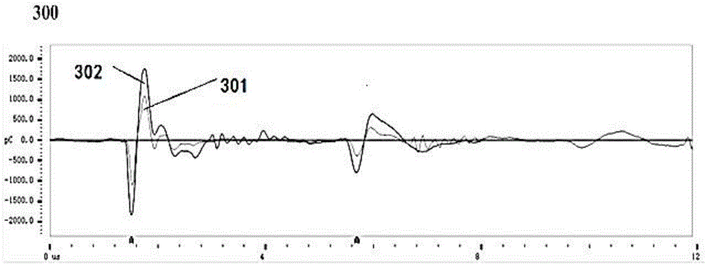
The invention discloses a method and system for determining a partial discharge source position. The method comprises the following steps: outputting the different shift of pulse signals at the end of a cable line for many times through a high-voltage lead, calibrating each shift of detection waveform signal, acquiring the verification waveform signal of each shift of detection waveform signal; performing partial discharge source detection on the cable line by using a way of applying voltage step by step, positioning the partial discharge source by using a time-domain pulse method, and acquiring a partial discharge source detection waveform corresponding a signal when the partial discharge source is located at the terminal of the cable line; performing equivalent correction on the discharge quantity calculated by the verification waveform to the same discharge quantity level of the terminal partial discharge source detection waveform by using a waveform normalization algorithm; and comparing the corrected verification waveform with the terminal partial discharge source detection waveform to determine whether the partial discharge source is at the head or the end of the detection cable line.

Description

technical field [0001] The present invention relates to the field of power cable line detection, and more specifically, to a method and system for determining the position of a partial discharge source. Background technique [0002] The partial discharge localization principle in the existing power cable line damped oscillatory wave partial discharge detection equipment generally adopts the time domain reflection method. If there is no matching impedance at the head, the partial discharge pulse will be reflected at the end, and the defect can be calculated according to the time difference between the first pulse transmitted along the measuring end measured at the measuring end and the pulse reflected at the other end and transmitted back to the measuring end The distance from the measurement end to locate the defective part. However, the time domain reflection method has its inherent defects, that is, when the partial discharge signal generated at the head end and the end o...

Claims


Application Information

Patent Timeline
IPC IPC(8): G01R31/12
CPCG01R31/1272
Inventor 王昱力蒙绍新夏荣刘家齐赵健康任广振徐立杨丹杨先进姜建周成钢王滔刘红武费婵李利红耿晓华
Owner CHINA ELECTRIC POWER RES INST
Learn More