
Combustor fuel nozzle and thermal protection structure thereof

A thermal protection structure, fuel nozzle technology, applied in combustion chambers, continuous combustion chambers, combustion methods, etc., can solve problems such as hindering fuel delivery, oxidative cracking, and increasing the number of nozzle repairs, so as to improve heat transfer performance and reduce fuel coking Possibility, effect of enhancing thermal protection performance

Active Publication Date: 2017-04-05
AECC COMML AIRCRAFT ENGINE CO LTD
View PDF7 Cites 12 Cited by
  • Summary
  • Abstract
  • Description
  • Claims
  • Application Information

AI Technical Summary

Problems solved by technology

Due to the limited flow rate of the fuel in the fuel inlet pipeline in the nozzle housing, it is easy to oxidize and crack under high temperature environment, and finally deposit coke inside the fuel pipe to block the nozzle, hinder the delivery of fuel, and increase the nozzle's efficiency. The number of repairs shortens the normal service life of the nozzle, which adversely affects the normal operation of the combustion chamber

Method used


Image

  • Combustor fuel nozzle and thermal protection structure thereof
  • Combustor fuel nozzle and thermal protection structure thereof
  • Combustor fuel nozzle and thermal protection structure thereof

Examples


Embodiment Construction

[0021] The present invention will be further described below in conjunction with specific embodiment and accompanying drawing, set forth more details in the following description so as to fully understand the present invention, but the present invention can obviously be implemented in many other ways different from this description, Those skilled in the art can make similar promotions and deductions based on actual application situations without violating the connotation of the present invention, so the content of this specific embodiment should not limit the protection scope of the present invention.

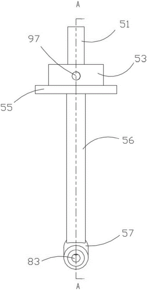
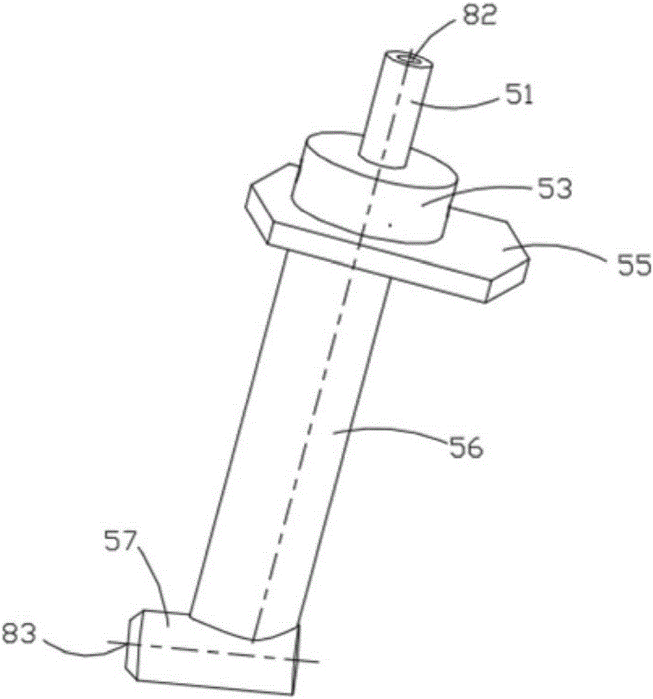
[0022] Figure 2 to Figure 4 It shows the thermal protection structure of the fuel nozzle of the combustion chamber according to an embodiment of the present invention. It should be noted that these and other subsequent drawings are only examples, which are not drawn according to the same scale, and should not be taken as limitations on the protection scope of the actual claims...


PUM


Abstract

The invention provides a combustor fuel nozzle and a thermal protection structure thereof. The thermal protection structure can reduce possibility that the nozzle is liable to coke fuel during an actual use process. The thermal protection structure comprises a thermal protection pipe and a heat exchange structure, wherein the thermal protection pipe is used for surrounding an oil inlet pipe; the inner wall surface of the thermal protection pipe is used for forming a thermal protection space together with the outer wall surface of the oil inlet pipe; the thermal protection space is divided into an air inlet part and an air outlet part, which are separated and located on two sides of the oil inlet pipe; the air inlet part and the air outlet part are used for forming a cooling air channel together with a pipe-wall inner cavity of an outlet section of the nozzle; the heat exchange structure is arranged in the thermal protection space and comprises a plurality of transverse rib plates and a plurality of longitudinal rib plates; the transverse rib plates are perpendicular to the flowing direction of cooling air; the longitudinal rib plates are radially distributed by taking the oil inlet pipe as a center and intersect the transverse rib plates respectively; and each transverse rib plate is provided with a plurality of airflow holes for allowing the cooling air to flow through.

Description

technical field [0001] The invention relates to a fuel nozzle and its thermal protection structure, in particular to a gas turbine fuel nozzle and its thermal protection structure. Background technique [0002] The fuel nozzle is one of the core components in the combustion chamber of an aero-engine. The fuel is supplied to the nozzle from the outside through the oil inlet pipeline, and is finally sprayed into the flame tube for combustion through a series of rotary atomization and other treatments of the nozzle. Due to the limited flow rate of the fuel in the fuel inlet pipeline in the nozzle housing, it is easy to oxidize and crack under high temperature environment, and finally deposit coke inside the fuel pipe to block the nozzle, hinder the delivery of fuel, and increase the nozzle's efficiency. The number of repairs shortens the normal service life of the nozzle, thus adversely affecting the normal operation of the combustion chamber. Contents of the invention [00...

Claims


Application Information

Patent Timeline
IPC IPC(8): F23R3/28
Inventor 胡莹超郭德三
Owner AECC COMML AIRCRAFT ENGINE CO LTD
Learn More