A method for optimizing performance parameters of a phased array antenna pattern and electronic equipment
A phased array antenna and optimization method technology, applied in the field of electronics, can solve the problem that performance parameters do not meet actual needs, etc., and achieve the effect of reducing the time for antenna darkroom testing and modifying amplitude weighted codes, considerable economic benefits, and improving performance parameters.
- Summary
- Abstract
- Description
- Claims
- Application Information
AI Technical Summary
Problems solved by technology
Method used
Image
Examples
Embodiment 1
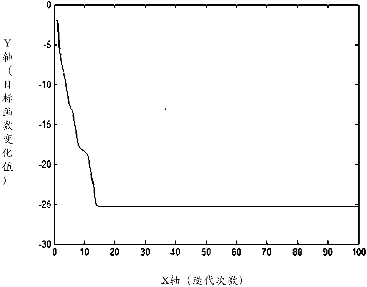
[0060] Please refer to figure 1 , an embodiment of the present invention provides a method for optimizing performance parameters of a phased array antenna pattern, including:
[0061] S101: Determine performance parameters of the phased array antenna pattern;
[0062] S102: Determine an objective function corresponding to the performance parameter of the phased array antenna pattern;
[0063] S103: Adjust the attenuation value of the T / R component of the phased array antenna to obtain a corresponding change value of the objective function;
[0064] S104: Based on the change value of the objective function, determine an optimal amplitude weighted iteration direction.
[0065] Wherein, the performance parameters specifically include: any one or a combination of side lobe levels, differential beam zero depths, and beam widths of the phased array antenna.
[0066] Wherein, the determination of the objective function corresponding to the performance parameters of the phased arra...
Embodiment 2
[0106] Please refer to Figure 4 , the embodiment of the present application also provides an electronic device, including:
[0107] a storage unit 401, configured to store at least one program module;
[0108] At least one processor 402, the at least one processor is used to determine the performance parameters of the phased array antenna pattern by obtaining and running the at least one program module; determine the performance parameters related to the phased array antenna pattern An objective function corresponding to the parameter; adjusting the attenuation value of the T / R component of the phased array antenna to obtain a change value of the objective function corresponding thereto; based on the change value of the objective function, determining an optimal amplitude weighted iteration direction.
[0109] Optionally, the performance parameters specifically include: any one or a combination of sidelobe levels, differential beam null depths, and beam widths of the phased...
Embodiment 3
[0121] Please refer to Figure 5 , the embodiment of the present application also provides an electronic device, including:
[0122] A first determination unit 501, configured to determine performance parameters of the phased array antenna pattern;
[0123] The second determination unit 502 is configured to determine an objective function corresponding to the performance parameter of the phased array antenna pattern;
[0124] The first adjustment unit 503 is configured to adjust the attenuation value of the T / R component of the phased array antenna, and obtain the change value of the objective function corresponding thereto;
[0125] The third determining unit 504 is configured to determine an optimal amplitude weighted iteration direction based on the change value of the objective function.
[0126] Optionally, the performance parameters specifically include: any one or a combination of sidelobe levels, differential beam null depths, and beam widths of the phased array ante...
PUM
 Abstract
Description
Claims
Application Information
 - R&D
- Intellectual Property
- Life Sciences
- Materials
- Tech Scout
- Unparalleled Data Quality
- Higher Quality Content
- 60% Fewer Hallucinations
Browse by: Latest US Patents, China's latest patents, Technical Efficacy Thesaurus, Application Domain, Technology Topic, Popular Technical Reports.
© 2025 PatSnap. All rights reserved.Legal|Privacy policy|Modern Slavery Act Transparency Statement|Sitemap|About US| Contact US: help@patsnap.com


