Low-temperature enthalpy increasing system and working method thereof
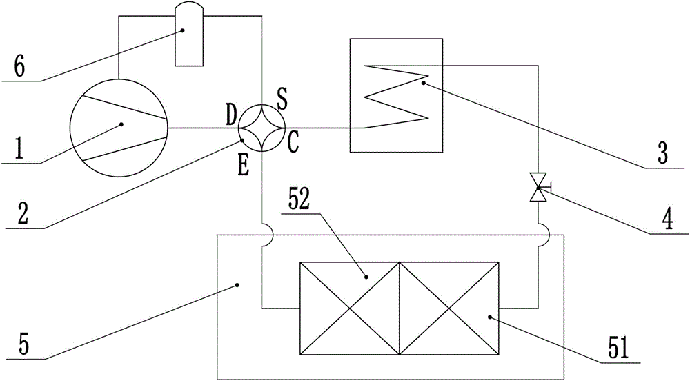
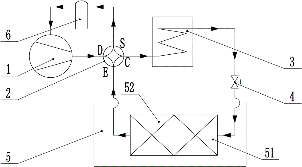
An enthalpy-increasing system and a working method technology are applied in the field of air-conditioning heat pumps, which can solve problems such as affecting the energy efficiency of the unit and reducing heat, and achieve the effects of increasing the amount of refrigerant circulation, increasing the heating capacity, and stabilizing the operation.
- Summary
- Abstract
- Description
- Claims
- Application Information
AI Technical Summary
Problems solved by technology
Method used
Image
Examples
Embodiment 1
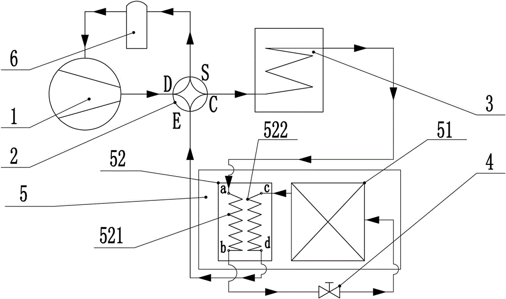
[0028] Embodiment one: see attached image 3 , each heat exchanger in the second area 52 includes a first heat exchange tube 521 and a second heat exchange tube 522, the first heat exchange tube 521 is provided with two interfaces a and b, and the second heat exchange tube 522 is provided with c and d two interfaces.
[0029] The connection relationship of the low-temperature enthalpy increasing system in the first embodiment is as follows: the compressor 1 is connected to the interface D of the four-way valve 2, the interface C of the four-way valve 2 is connected to the condenser 3, and the condenser 3 is connected to the first heat exchange tube 521 Interface a, interface b of the first heat exchange tube 521 is connected to the throttling component 4, the throttle component 4 is connected to the heat exchanger in the first area 51, and the heat exchanger in the first area 51 is connected to the interface c of the second heat exchange tube 522 , the interface d of the seco...
Embodiment 2
[0032] Embodiment two: see attached Figure 4 , each heat exchanger in the second area 52 includes a first heat exchange tube 521 and a second heat exchange tube 522, the first heat exchange tube 521 is provided with two interfaces a and b, and the second heat exchange tube 522 is provided with c and d two interfaces.
[0033] The connection relationship of the low-temperature enthalpy increasing system in the second embodiment is as follows: the compressor 1 is connected to the interface D of the four-way valve 2, the interface C of the four-way valve 2 is connected to the condenser 3, and the condenser 3 is connected to the throttling component 4, throttling Part 4 is connected to the heat exchanger in the first area 51, the heat exchanger in the first area 51 is connected to the interface b of the first heat exchange tube 521, and the interface c of the second heat exchange tube 522 is connected to the auxiliary heat pipe for transferring auxiliary heat from the interface ...
Embodiment 3
[0036] Embodiment three: see attached Figure 5 , each heat exchanger in the second area 52 includes a third heat exchange tube 523 and a heat exchange tank 524, the auxiliary heat is placed in the heat exchange tank 524, and the third heat exchange tube 523 is immersed in the auxiliary heat of the heat exchange tank 524 Inside.
[0037] The connection relationship of the low-temperature enthalpy increasing system in the third embodiment is as follows: the compressor 1 is connected to the interface D of the four-way valve 2, the interface C of the four-way valve 2 is connected to the condenser 3, and the condenser 3 is connected to the throttling component 4, and the throttling Component 4 is connected to the heat exchanger in the first area 51, the heat exchanger in the first area 51 is connected to the third heat exchange pipe 523, and the heat exchange tank 524 is respectively connected to the auxiliary heat pipe and the heat exhaust pipe for discharging the auxiliary heat ...
PUM
 Abstract
Description
Claims
Application Information
 - R&D Engineer
- R&D Manager
- IP Professional
- Industry Leading Data Capabilities
- Powerful AI technology
- Patent DNA Extraction
Browse by: Latest US Patents, China's latest patents, Technical Efficacy Thesaurus, Application Domain, Technology Topic, Popular Technical Reports.
© 2024 PatSnap. All rights reserved.Legal|Privacy policy|Modern Slavery Act Transparency Statement|Sitemap|About US| Contact US: help@patsnap.com


