
Ultrasonic flaw detection device and ultrasonic flaw detection method

A flaw detection device, ultrasonic technology, applied in the use of sound waves/ultrasonic waves/infrasonic waves for material analysis, measuring devices, temperature recording methods, etc., can solve problems such as pipe circumference deviation

Active Publication Date: 2017-03-22
JFE STEEL CORP
View PDF8 Cites 7 Cited by
  • Summary
  • Abstract
  • Description
  • Claims
  • Application Information

AI Technical Summary

Problems solved by technology

[0004] However, electric welded steel pipes are subjected to various forces on the manufacturing line, so the welded seam is not necessarily located on the center line of the sensor head, and there are cases where it is offset in the direction of the pipe circumference relative to the center line of the sensor head

Method used


Image

  • Ultrasonic flaw detection device and ultrasonic flaw detection method
  • Ultrasonic flaw detection device and ultrasonic flaw detection method
  • Ultrasonic flaw detection device and ultrasonic flaw detection method

Examples


Embodiment Construction

[0036] Hereinafter, the configuration and operation of an ultrasonic flaw detection device according to an embodiment of the present invention will be described with reference to the drawings.

[0037] 〔structure〕

[0038] First, refer to figure 1 , figure 2 , and the structure of the ultrasonic flaw detection apparatus according to one embodiment of the present invention will be described.

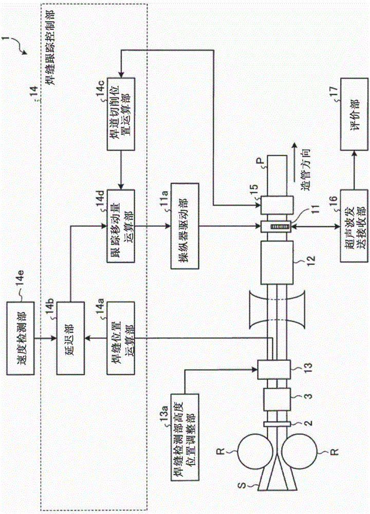
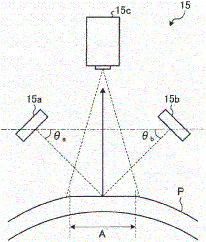
[0039] figure 1 It is a schematic diagram showing the overall structure of an ultrasonic flaw detection device according to an embodiment of the present invention. figure 2 yes means figure 1 A schematic diagram of the structure of the weld bead cutting zone detection section shown.

[0040] Such as figure 1As shown, the ultrasonic flaw detection device 1 according to one embodiment of the present invention is a device for ultrasonic flaw detection of a welded seam portion of an electric resistance welded steel pipe P made of a steel plate S formed into a tubular shape by rolls R ...


PUM


Abstract

This ultrasonic flaw detection device (1) is provided with: a sensor head (11) for ultrasonic flaw detection that is disposed downstream of a seam detection unit (13); a seam position calculation unit (14a) that calculates a seam position and bead cutting position of a seam-welded pipe (P) using a thermal image of a weld seam portion captured by the seam detection unit (13); a bead cut band detection unit (15) that is disposed just before or just after the sensor head (11) for ultrasonic flaw detection and detects a bead cut band of the seam-welded pipe (P); a bead cutting position calculation unit (14c) that calculates the bead cutting position of the seam-welded pipe (P) on the basis of the bead cut band detected by the bead cut band detection unit (15); and a following movement amount calculation unit (14d) that calculates the amount of following movement of the sensor head (11) for ultrasonic flaw detection using the seam position and bead cutting position calculated by the seam position calculation unit (14a) and the bead cutting position calculated by the bead cutting position calculation unit (14c).

Description

technical field [0001] The present invention relates to an ultrasonic flaw detection device and an ultrasonic flaw detection method for ultrasonic flaw detection of welded seam portions of electric welded steel pipes. Background technique [0002] Generally, an electric resistance welded steel pipe is manufactured by forming a steel sheet into a tubular shape, and welding and joining both ends of the steel sheet in the width direction while being pressed against each other. In the manufacturing process of such an electric welded steel pipe, in order to obtain good welding quality, the electric welded steel pipe uses an ultrasonic flaw detection device to perform ultrasonic flaw detection on the welded seam part, and anneals the welded seam part through a weld seam annealing furnace (for welding Tempering treatment is carried out on the welded seam portion close to the quenched state), thereby proceeding to productization. [0003] When ultrasonic flaw detection is performed...

Claims


Application Information

Patent Timeline
Patent Type & Authority Applications(China)
IPC IPC(8): G01N29/265
CPCB23K31/125G01N29/223G01N29/265G01N2291/2675G01J5/48
Inventor 松井穣坂下重人米本笃志
Owner JFE STEEL CORP
Learn More