Wire rope flaw detection device
A flaw detection device, wire rope technology, applied in the direction of material magnetic variables, etc., can solve the problems of leakage magnetic flux, increase and so on
- Summary
- Abstract
- Description
- Claims
- Application Information
AI Technical Summary
Problems solved by technology
Method used
Image
Examples
no. 1 Embodiment approach
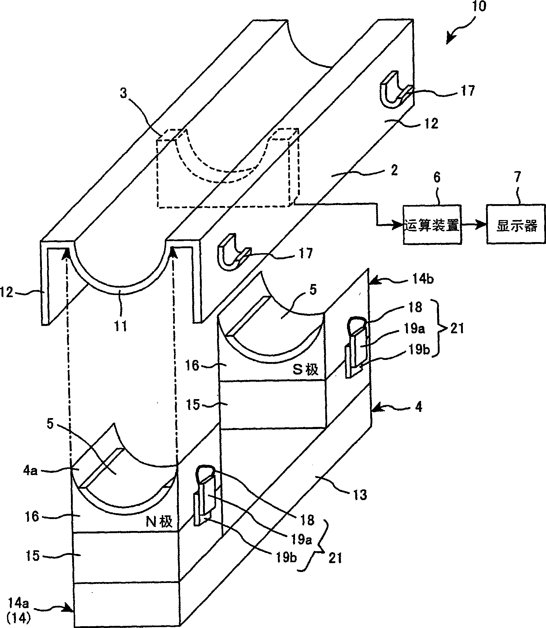
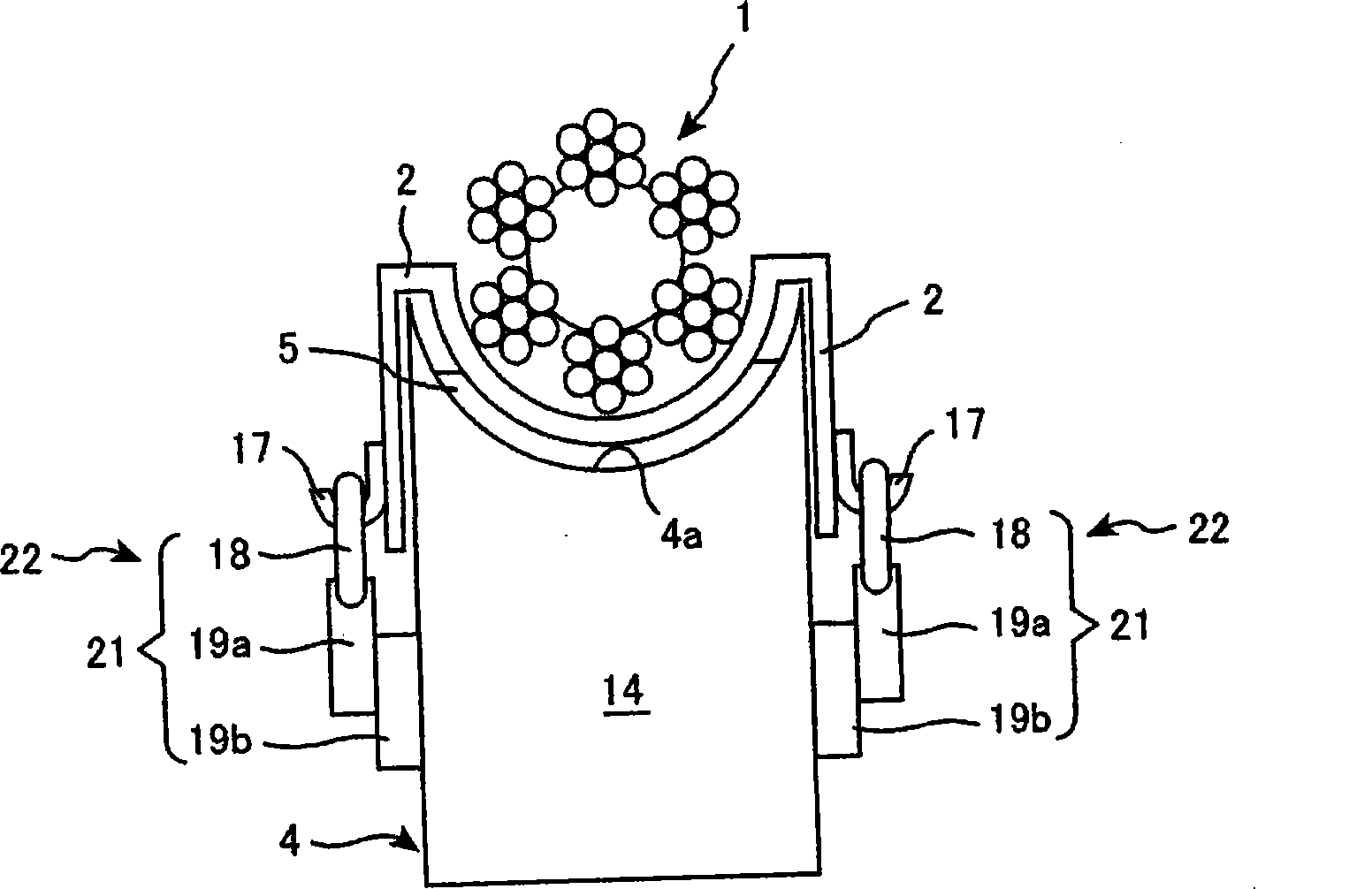
[0038] figure 1 It is an exploded perspective view showing a wire rope flaw detection device (hereinafter referred to as a flaw detection device) according to a preferred embodiment, figure 2 yes figure 1 Sectional view of the flaw detection device shown.
[0039] Such as figure 1 As shown, the flaw detection device 10 has a guide wire rope 1 ( figure 2 As shown), the guiding device 2, the magnetization unit 4 for magnetizing the steel wire rope 1, and the magnetic flux detection unit 3 for detecting the leakage magnetic flux of the steel wire rope 1.
[0040] The guide 2 is formed of a non-magnetic plate material having a semi-cylindrical recess 11 in which the wire rope 1 is held so as to be movable (slidable) in the wire rope length direction. Both sides of the concave portion 11 of the guide 2 are bent so that the magnetization unit 4 can be fitted (to form both side portions 12 , 12 ).
[0041] The magnetization unit 4 is composed of a permanent magnet type U-shape...
no. 2 Embodiment approach
[0077] Hereinafter, a second embodiment which is a preferred embodiment of the present invention will be described with reference to the drawings.
[0078] Such as Figure 8 As shown, the basic structural parts of the wire rope flaw detection device 30 of this embodiment and figure 1 The above-mentioned flaw detection device 10 shown is roughly the same, and for the same structural part, use and figure 1 The same symbols indicate that the difference between this embodiment and the previous embodiment is that the figure 1 In the shown spacer 5 , a gap (air gap) 31 is provided between the magnetic pole surface 4 a of the magnetization unit 4 and the guide device 2 , and the length of the gap can be adjusted.
[0079] That is, in the flaw detection device 30 of this embodiment, a gap 31 is formed between the magnetization unit 4 and the guide device 2, and a mechanism for adjusting the gap length of the gap 31 is provided, and the magnetic flux adjustment is configured by this ...
no. 3 Embodiment approach
[0087] A third embodiment which is a preferred embodiment of the present invention will be described below.
[0088] Such as Figure 10 (a) and Figure 10 As shown in (b), the basic structure of the wire rope flaw detection device 40 of this embodiment is the same as that of the flaw detection device 20 in the previous embodiment, but the difference is that in this embodiment, as the guide device 2 and the magnetization unit 4 The mechanism for forming a length-variable gap between the magnetic pole faces 4a is provided so that the frame 41 (made of non-magnetic material) for accommodating the magnetizing unit 4 and the guide device 2 are integrated, and the magnetizing unit 4 is adjusted within the frame 41. And be fixed on the mechanism (arbitrary adjustment mechanism 42 of magnetization unit) on arbitrary height. That is, in the present embodiment, the magnetic flux adjustment unit is constituted by the magnetization unit arbitrary adjustment mechanism 42 , which is a mec...
PUM
 Abstract
Description
Claims
Application Information
 - R&D
- Intellectual Property
- Life Sciences
- Materials
- Tech Scout
- Unparalleled Data Quality
- Higher Quality Content
- 60% Fewer Hallucinations
Browse by: Latest US Patents, China's latest patents, Technical Efficacy Thesaurus, Application Domain, Technology Topic, Popular Technical Reports.
© 2025 PatSnap. All rights reserved.Legal|Privacy policy|Modern Slavery Act Transparency Statement|Sitemap|About US| Contact US: help@patsnap.com


