
Electric vehicle charging station and electric power system

A technology for electric vehicles and charging stations, which is applied in the field of new energy, and can solve problems affecting the promotion and application of electric vehicles, the inability to set up electric vehicle charging stations, and the impact of electric vehicle charging stations.

Inactive Publication Date: 2017-03-22
QINGHAI CONTEMPORARY AMPEREX TECH
View PDF3 Cites 10 Cited by
  • Summary
  • Abstract
  • Description
  • Claims
  • Application Information

AI Technical Summary

Problems solved by technology

[0002] Under the government's vigorous promotion of electric vehicles and other electric vehicle industries, my country's electric vehicle industry has entered a period of rapid development, but the charging behavior of a large number of electric vehicles will have a greater impact on the power grid, directly using the existing power grid as a new energy source. There is a certain bottleneck in the development of electric vehicle charging
[0003] At present, the existing electric vehicle charging station adopts a grid-connected design. If the grid fails, the charging station cannot work, and the electric vehicle charging station cannot be installed in a place without grid power supply, that is to say, the electric vehicle charging Stations are easily affected by the power grid, which will affect the promotion and application of electric vehicles

Method used


Image

  • Electric vehicle charging station and electric power system
  • Electric vehicle charging station and electric power system

Examples


Embodiment Construction

[0055] The present application will be described in further detail below through specific embodiments and in conjunction with the accompanying drawings.

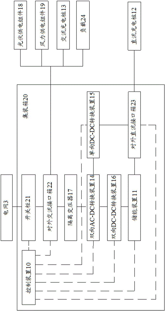
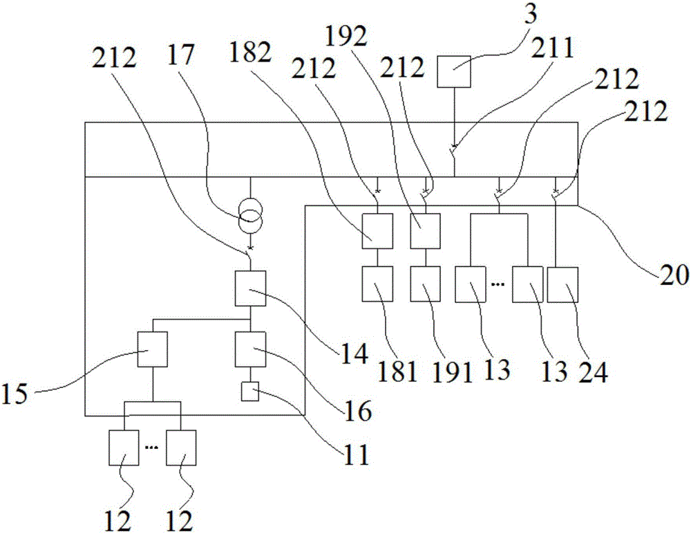
[0056] Such as figure 1 with figure 2 As shown, the embodiment of the present application provides an electric vehicle charging station, which can charge electric vehicles and electric motorcycles, and can also charge other components that need to be charged. The electric vehicle charging station includes a control device 10, an energy storage device 11 electrically connected to the control device 10, and a charging pile. The energy storage device 11 can be connected to the grid 3 and can store the electric energy of the grid 3, and the charging The pile can be electrically connected to the grid 3 and the energy storage device 11 , and can obtain electric energy from at least one of the grid 3 and the energy storage device 11 .

[0057] Specifically, the connection between the charging pile and the grid 3 and the energy s...


PUM


Abstract

The invention relates to the technical field of new energy, particularly to an electric vehicle charging station and an electric power system. The electric vehicle charging station comprises a control apparatus, an energy storage apparatus and a charging pile, wherein the energy storage apparatus can be electrically connected with a power grid and used for storing electric energy supplied by the power grid and supplying power for the charging pile; the energy storage apparatus is electrically connected with the charging pile to form a first charging circuit; the charging pile can be electrically connected with the power grid to form a second charging circuit; and the control apparatus can be electrically connected with the energy storage apparatus, the charging pile and the power grid, and used for controlling the on and off of the first charging circuit and the second charging circuit. By controlling the on and off between the charging pile and the power grid and the energy storage apparatus through the control apparatus, the electric vehicle charging station can be adapted to different environments, namely, the control apparatus still can control the energy storage apparatus to charge the charging pile even if the power grid is in power failure or the electric vehicle charging station is disconnected from the power grid, so that the influence on the electric vehicle charging station from the power grid is effectively relieved.

Description

technical field [0001] The present application relates to the field of new energy technology, in particular to an electric vehicle charging station and a power system. Background technique [0002] With the government's vigorous promotion of electric vehicles and other electric vehicle industries, my country's electric vehicle industry has entered a period of rapid development, but the charging behavior of a large number of electric vehicles will have a greater impact on the power grid, directly using the existing power grid as a new energy source. There is a certain bottleneck in the development of electric vehicle charging. [0003] At present, the existing electric vehicle charging station adopts a grid-connected design. If the grid fails, the charging station cannot work, and the electric vehicle charging station cannot be installed in a place without grid power supply. That is to say, the electric vehicle charging Stations are easily affected by the power grid, which wi...

Claims


Application Information

Patent Timeline
IPC IPC(8): H02J7/00H02J3/32
CPCH02J7/0027H02J3/32
Inventor 甘生元
Owner QINGHAI CONTEMPORARY AMPEREX TECH
Learn More