Microstrip isolator

An isolator and microstrip technology, applied in the directions of waveguide devices, electrical components, circuits, etc., can solve the problems of the gap between the bottom plate and the external circuit, the influence of the planeness of the bottom plate, and the use of the isolator.

Active Publication Date: 2017-03-22
SUZHOU ARTIARM ROBOT CO LTD
View PDF5 Cites 3 Cited by
  • Summary
  • Abstract
  • Description
  • Claims
  • Application Information

AI Technical Summary

Problems solved by technology

[0003] In the prior art, the microstrip isolator includes a cylinder with a cover, a bottom plate, and a resistor. The cylinder with a cover is covered on the bottom plate, and the inner cavity of the cylinder with a cover is arranged with an intracavity component. The cavity The inner element includes a circuit part, and the three pins of the circuit part protrude outward, and respectively penetrate through the corresponding avoidance hole grooves on the outer ring surface of the covered cylinder and protrude on the outer ring surface of the covered cylinder, wherein One pin is externally connected to a resistor. In addition, the base plate corresponding to the existing cylinder with a cover must be a metal structure, and the base plate is fixed on the end surface of the circuit board. This structure is designed to ensure that the base plate can fully contact the external circuit. , to ensure the grounding performance of the entire structure. However, due to the defects in the manufacturing process of the base plate, the flatness of the base plate is affected, and there may be a gap between the base plate and the external circuit, which will affect the use of the entire isolator.

Method used


Image

  • Microstrip isolator
  • Microstrip isolator
  • Microstrip isolator

Examples


specific Embodiment 1

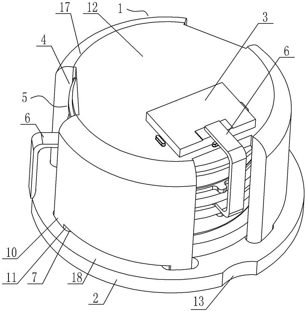
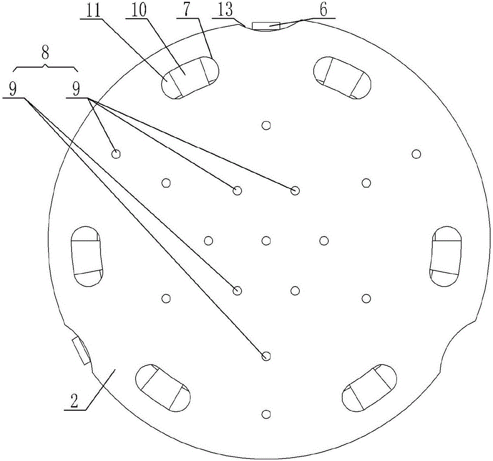
[0037] The monomer isolator of specific embodiment one, see figure 1 , figure 2: The resistor 3 is located on the upper end surface of the cover plate 12 of the covered cylinder 1, and the pin 6 corresponding to the connection resistor 3 passes through the corresponding avoidance groove 4 and then is bent upwards and then connected to the resistor 3. The upper end surface of the cover plate 12 corresponds to The position of the resistor 3 is coated with solder paste, and the resistor 3 is fixedly connected to the solder paste at the corresponding position by reflow soldering (this structure is an existing mature structure, not shown in the figure), and the pin 6 of the non-connected resistor 3 runs through the corresponding The avoidance groove 4 is bent downwards, and its lower end is located at the pin avoidance groove 13 corresponding to the base plate 2. The surface of the pin avoidance groove 13 is provided with copper foil, and the lower ends of the pins 6 of the two no...

Embodiment 1

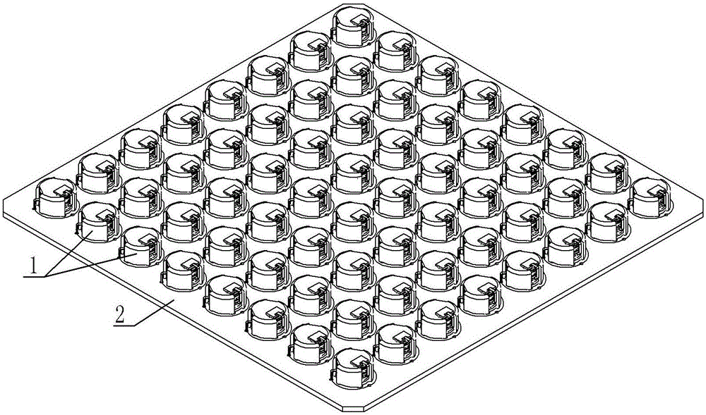
[0038] The matrix isolator of embodiment one, see image 3 : The shape of the bottom plate 1 is a rectangle, and a plurality of metal connection parts 7 corresponding to a single isolator, a central metal connection area 8, a positioning hole groove 11, and a pin avoidance groove 13 are combined to form a processing unit. A plurality of processing units are arranged, and a single covered cylinder 1 with an internal element 5 is positioned one by one in the corresponding positioning hole groove 11 on the corresponding processing unit, and the lower end of the pin 6 is located in the pin avoidance groove at the corresponding position In 13, the rectangular bottom plate 1 is specifically a PCB board, and matrix-type isolators are arranged on the rectangular PCB board to meet various needs and realize the use of multiple frequency bands, so that the isolators in the entire device can be arranged in a centralized manner, saving A lot of space for equipment.

specific Embodiment 2

[0039] The monomer isolator of specific embodiment two, see Figure 4 : Resistor 3 is set on the bottom plate 1, the pin 6 corresponding to the connection resistor 3 penetrates the corresponding avoidance groove 4 and then bends down to connect to the resistor 3, and the pin 6 of the non-connected resistor 3 penetrates the corresponding avoidance groove 4 and then goes downward Bend, the lower end of which is located in the pin avoidance groove 13 corresponding to the base plate 2, the groove surface of the pin avoidance groove 13 is provided with copper foil, and the lower ends of the pins 6 of the two non-connected resistors 3 are lapped on the copper foil.


PUM


Abstract

The invention provides a microstrip isolator, which can ensure sufficient grounding of the isolator and an external circuit, thereby ensuring normal operations of the isolator. The microstrip isolator comprises a cylinder with a cover, a base plate and a resistor, wherein the circumferential surface of the cylinder with a cover is provided with avoidance slots, the bottom part of the cylinder with a cover is fixedly installed on the base plate, a cavity formed by combining the cylinder with a cover and the base plate is internally provided with an intracavity element, the intracavity element comprises a circuit portion, three outward protruding pins of the circuit portion penetrate through the corresponding avoidance slots, and the tail end of one of the pins is externally connected with the resistor. The microstrip isolator is characterized in that the base plate is specifically of a metal-plastic mixed material structure, the base plate is provided with metal connecting portions at positions corresponding to fixedly installed portions of the cylinder with a cover, the base plate is provided with a central metal connecting region at the central position, and each metal connecting portion is connected to the central metal connecting region through a metal wire/metal strip embedded in the plastic.

Description

technical field [0001] The invention relates to the technical field of wireless communication equipment, in particular to a microstrip isolator. Background technique [0002] In the existing wireless communication system, the transmitter is an important part, which is composed of a power amplifier (PA), a coupler, a circulator / isolator, a connector, a duplexer and an antenna, among which the coupler is used For the related monitoring function of the link, the circulator or isolator is used to protect the power amplifier tube, and the connector transmits the output signal to the duplexer. It is a similar design in the wireless field, but with the development of wireless communication, the requirements for miniaturization are getting higher and higher. [0003] In the prior art, the microstrip isolator includes a cylinder with a cover, a bottom plate, and a resistor. The cylinder with a cover is covered on the bottom plate, and the inner cavity of the cylinder with a cover is...

Claims


Application Information

Patent Timeline
Patent Type & Authority Applications(China)
IPC IPC(8): H01P1/36
CPCH01P1/36
Inventor 蒋剑
Owner SUZHOU ARTIARM ROBOT CO LTD
Why Eureka
Try Eureka