
Display system and applicable head-mounted display thereof

A display system and integral column technology, applied in instruments, optical components, optics, etc., can solve problems such as power consumption, light waste, and the inability to effectively reduce the volume of head-mounted displays

Active Publication Date: 2017-03-22
DELTA ELECTRONICS INC
View PDF7 Cites 1 Cited by
  • Summary
  • Abstract
  • Description
  • Claims
  • Application Information

AI Technical Summary

Problems solved by technology

Because the area of ​​the organic light-emitting diode panel is large, and the pixels of the panel are self-illuminating omnidirectional illumination, not only will the volume of the head-mounted display not be effectively reduced, but also a large amount of light will be caused due to the characteristics of omnidirectional illumination. waste, which in turn leads to a large power consumption

Method used


Image

  • Display system and applicable head-mounted display thereof
  • Display system and applicable head-mounted display thereof
  • Display system and applicable head-mounted display thereof

Examples


Embodiment Construction

[0052] Some typical embodiments embodying the features and advantages of the present invention will be described in detail in the description in the following paragraphs. It should be understood that the present invention can have various changes in different aspects without departing from the scope of the present invention, and the descriptions and illustrations therein are used as illustrations in nature rather than limiting the present invention .

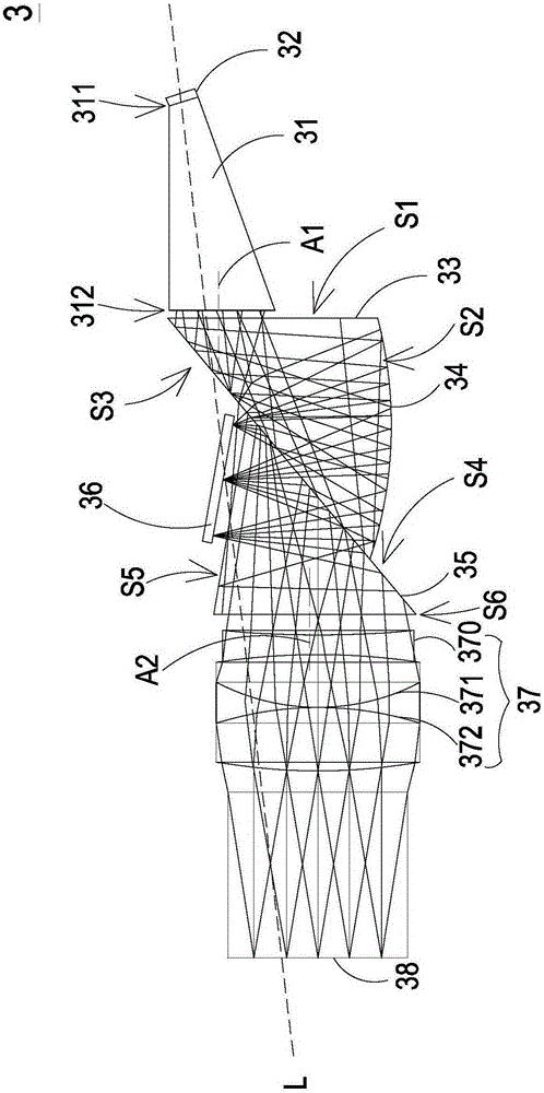
[0053] see image 3 , which is a schematic diagram showing the structure of a display system according to a preferred embodiment of the present invention. Such as image 3 As shown, the display system 3 of the present invention includes an optical integrating column 31, a solid-state light-emitting element 32, a first total internal reflection prism 33, a reflector 34, a second total internal reflection prism 35, a digital micromirror device (DigitalMicromirror Device, DMD) 36 and eyepiece 37. Wherein, the solid-state light ...


PUM


Abstract

The invention relates to a display system, and the system comprises an optical integral column, a solid state light-emitting element, a first total internal reflection prism, a reflector, a second total internal reflection prism, a digital micromirror device, and an ocular lens. The solid state light-emitting element is disposed at an inlet end of the optical integral column. The first total internal reflection prism is provided with a first surface, a second surface and a third surface, wherein the first surface is adjacent to the outlet end of the optical integral column. The reflector is disposed on the second surface. The second total internal reflection prism is provided with a fourth surface, a fifth surface and a sixth surface, wherein the fourth surface contacts with the third surface. The digital micromirror device is disposed to be adjacent to the fifth surface. The ocular lens is adjacent to the sixth surface. Light enters the digital micromirror device along an illuminating optical path, and then is projected to an imaging surface along an imaging optical path. Therefore, the size of the display system can be effectively reduced.

Description

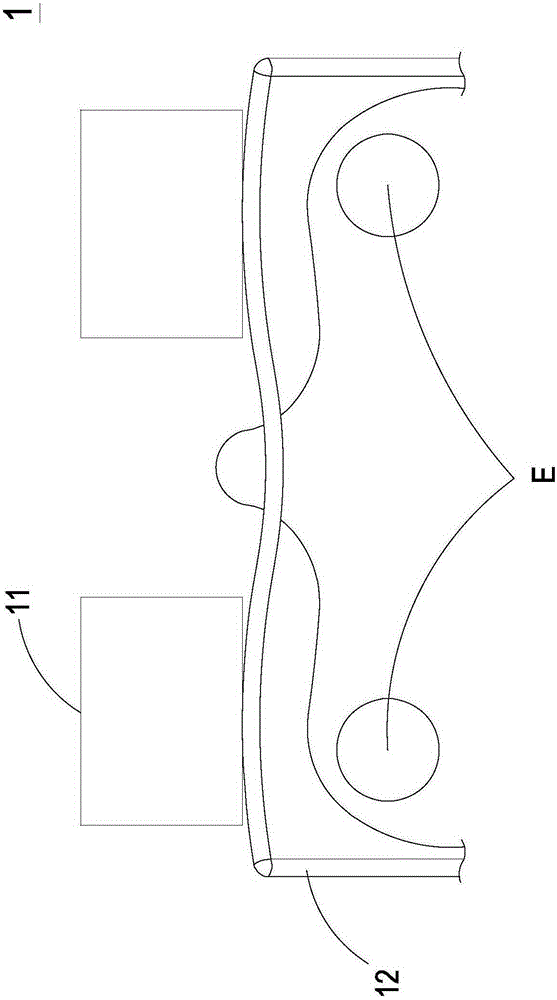
technical field [0001] The present invention relates to a display system, in particular to a display system and a head-mounted display applicable thereto. Background technique [0002] In recent years, head-mounted displays and near-eye displays have become a research and development direction of technological products, which are expected to bring more convenient life to users, and are even further applied to the Internet of Things. [0003] Generally speaking, the current head-mounted displays are mostly presented in the shape of glasses. see figure 1 , which shows a schematic diagram of the structure of a conventional head-mounted display. Such as figure 1 As shown, the current traditional head-mounted display 1 usually has an optical device 11 arranged on the spectacle frame 12, and through the design of the optical path, the image or light can be projected into the user's eyes E, so that the user can see the image. However, due to the limitation of the thickness of t...

Claims


Application Information

Patent Timeline
IPC IPC(8): G02B27/01
CPCG02B27/0101G02B27/0172G02B2027/0178
Inventor 黄俊杰
Owner DELTA ELECTRONICS INC
Learn More