A steel frame continuous collapse dynamic test device
A dynamic test, steel frame technology, applied in the direction of measuring devices, machine/structural component testing, instruments, etc., can solve the problems of laboratory damage, slow movement of loading parts, etc., and achieve the effect of strong destructiveness and low site requirements
- Summary
- Abstract
- Description
- Claims
- Application Information
AI Technical Summary
Problems solved by technology
Method used
Image
Examples
Embodiment 1
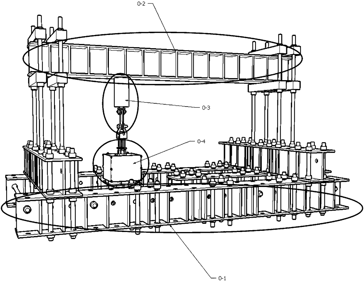
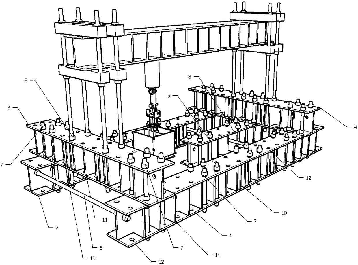
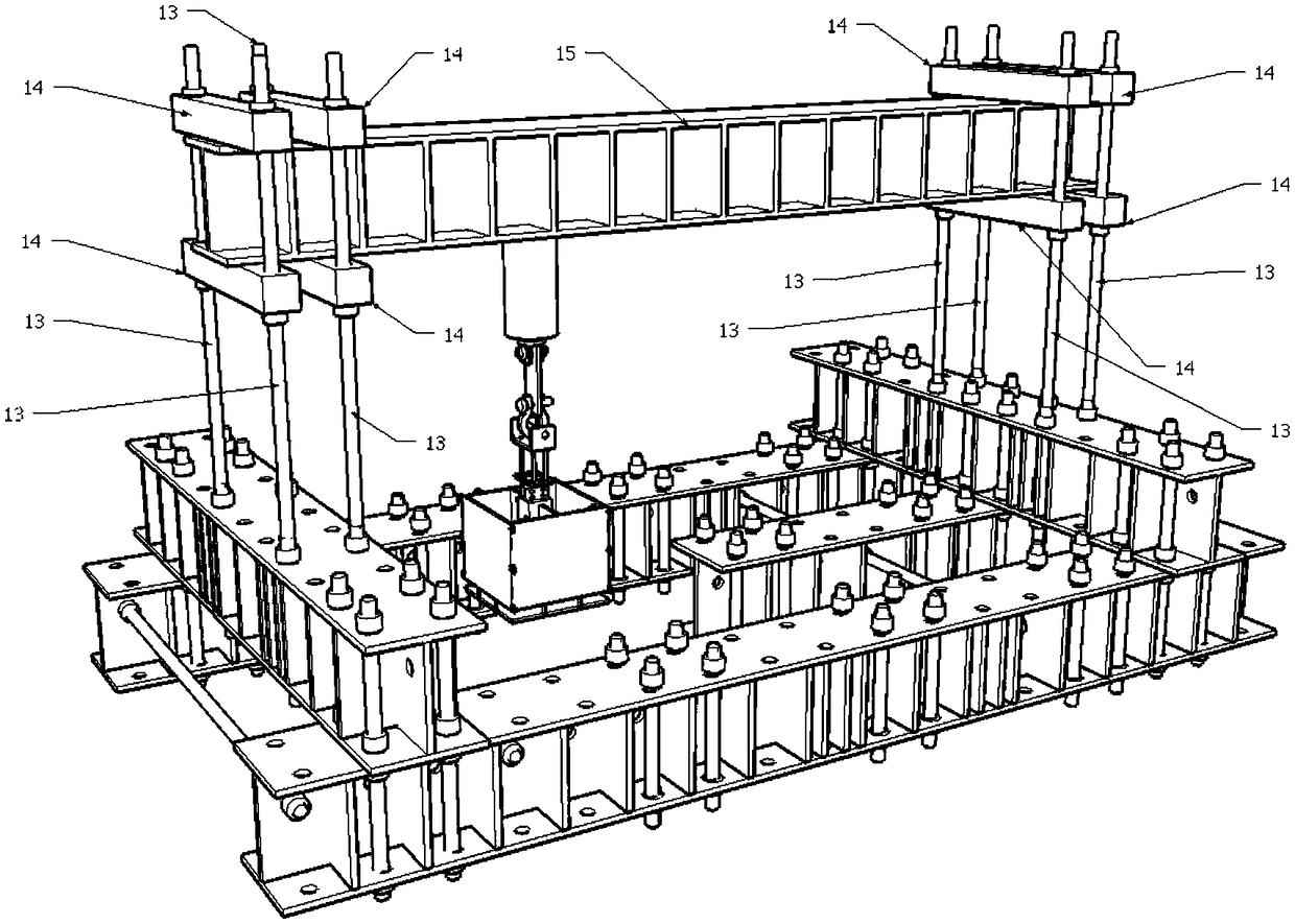
[0050] Such as Figure 6 As shown in Fig. 1, a steel frame continuous collapse dynamic test set is carried out, and the experiment conducted is a slab-column structure experiment. The foundation part does not contain short foundation steel beams 6 without additional stiffeners. During installation, first fix the vertical lead screw 7 at the corresponding required position of the hoisted foundation steel beams 1, 2, 5, then place the foundation steel beams 1, 2, 5 on the test site, place the foundation steel beams 1, 2 , 5. Lift the upper foundation steel beams 3, 4 and fix them with a vertical screw 7. Horizontal lead screw 8 is installed on foundation steel beam side. Hoist the test piece to the foundation part 0-1, and fix it with the vertical screw 7. Install the vertical support screw 13 to the predetermined bearing position 9, screw in the nut to the predetermined position of the vertical support screw 13, first hoist all the lower solid steel blocks 14, and hoist the ...
Embodiment 2
[0053] Such as Figure 7As shown in Fig. 1, a steel frame continuous collapse dynamic test set is carried out, and the experiment conducted is a slab-column structure experiment. The foundation part does not contain the horizontal lead screw 8 . During installation, first fix the vertical lead screw 7 at the corresponding required position of the hoisted foundation steel beams 3, 4, 5, 6, then place the foundation steel beams 3, 4, 5, 6 on the test site, The upper parts of the beams 3, 4, 5, and 6 are hoisted to the upper foundation steel beams 1, 2, and fixed with a vertical screw 7. Hoist the test piece to the foundation part 0-1, and fix it with the vertical screw 7. Install the vertical support screw 13 to the predetermined bearing position 9, screw in the nut to the predetermined position of the vertical support screw 13, first hoist all the lower solid steel blocks 14, and hoist the steel hanging beam 15 to the lower solid steel block 14, All upper solid steel blocks ...
Embodiment 3
[0056] Such as Figure 8 As shown in Fig. 1, a steel frame continuous collapse dynamic test set is carried out, and the experiment conducted is a slab-column structure experiment. The foundation part does not include short foundation steel beams 5, 6 without additional stiffeners. During installation, first fix the vertical lead screw 7 at the corresponding required position of the hoisted foundation steel beams 1, 2, 3, and 4, then place the foundation steel beams 1, 2, 3, and 4 on the test site, Horizontal lead screw 8 is installed on beam 1,2,3,4 side. Hoist the test piece to the foundation part 0-1, and fix it with the vertical screw 7. Install the vertical support screw 13 to the predetermined bearing position 9, screw in the nut to the predetermined position of the vertical support screw 13, first hoist all the lower solid steel blocks 14, and hoist the steel hanging beam 15 to the lower solid steel block 14, All upper solid steel blocks 14 are hoisted on the steel su...
PUM
 Abstract
Description
Claims
Application Information
 - Generate Ideas
- Intellectual Property
- Life Sciences
- Materials
- Tech Scout
- Unparalleled Data Quality
- Higher Quality Content
- 60% Fewer Hallucinations
Browse by: Latest US Patents, China's latest patents, Technical Efficacy Thesaurus, Application Domain, Technology Topic, Popular Technical Reports.
© 2025 PatSnap. All rights reserved.Legal|Privacy policy|Modern Slavery Act Transparency Statement|Sitemap|About US| Contact US: help@patsnap.com


