Pulse backflush valve

A technology of pulse blowback and valve body, which is applied in the direction of valve lift, valve details, valve device, etc., can solve the problems of air in the injection pipe, affecting the service life, and gas flowing into the injection pipe, so as to facilitate air intake and improve the sealing effect Effect

Inactive Publication Date: 2017-03-22
常州市康安环保设备有限公司
View PDF0 Cites 0 Cited by
  • Summary
  • Abstract
  • Description
  • Claims
  • Application Information

AI Technical Summary

Problems solved by technology

[0002] Pulse valve refers to a diaphragm valve that can be controlled by electromagnetic or pneumatic pilot valves and can instantly open and close high-pressure air sources to generate pulses; the pulse valve is the main component of the bag filter, and the injection can reach more than 1 million times; the current pulse valve The connection between the gas bag and the blowing pipe is blocked by a diaphragm, but the sealing effect of the diaphragm is not strong, and it is easy to make the gas in the gas bag flow into the blowing pipe, causing the blowing pipe to be in a state of gas for a long time; and the diaphragm is easily damaged, which affects the use life

Method used


Image

  • Pulse backflush valve
  • Pulse backflush valve

Examples


Embodiment Construction

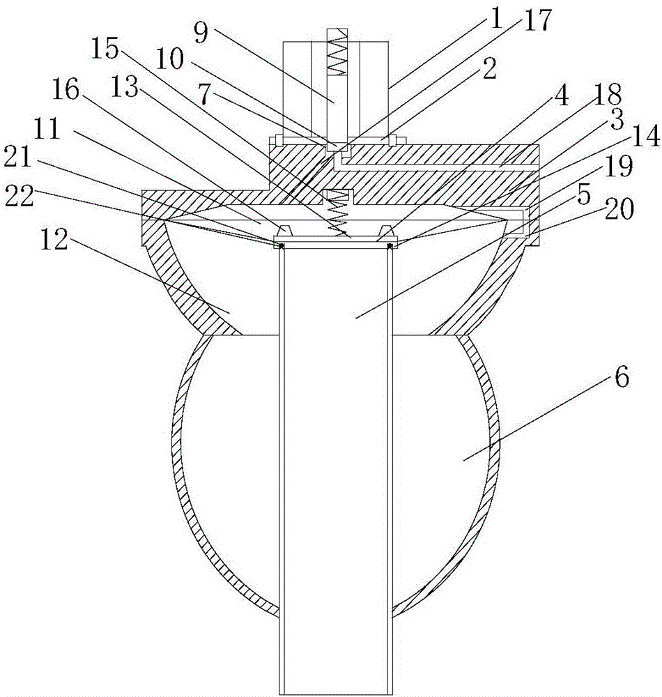
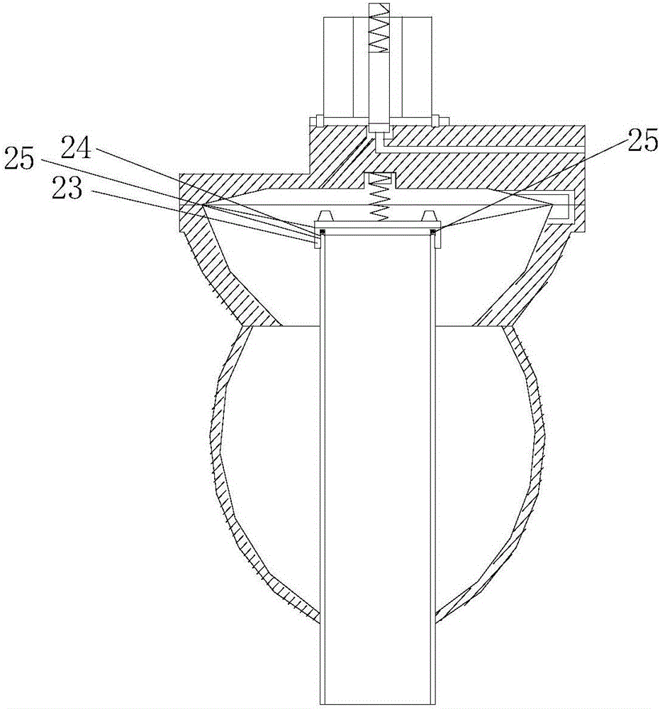
[0015] see figure 1 As shown, a pulse blowback valve is characterized in that it includes a solenoid valve 1, a valve cover 2, a valve body 3, a diaphragm 4, an injection port 5, and an air bag 6; the top of the valve body is provided with a first chamber 7. There is a second chamber at the bottom; a movable valve core 9 is provided in the solenoid valve, and the valve core is connected to the rubber pad 10 extending into the first chamber; the diaphragm divides the second chamber into Upper chamber 11 and lower chamber 12, the top surface of the diaphragm is provided with an upper pressure plate 13, and the bottom surface is provided with a lower pressure plate 14 covering the blowing port; the lower chamber is connected with the air bag; the valve body is also provided with a communication The through holes 17 of the first and second chambers, the first chamber is provided with a pressure relief hole 18, the upper chamber in the second chamber is provided with a constant pre...


PUM


Abstract

The invention relates to the technical field of pulse backflush valves, in particular to a pulse backflush valve. The pulse backflush valve comprises an electromagnetic valve body, a valve deck, a valve body, a membrane, a jetting port and an air pocket. A first cavity is formed in the top end of the valve body. A second cavity is formed in the bottom end of the valve body. A movable valve core is arranged in the electromagnetic valve body and connected with a rubber mat extending into the first cavity. The second cavity is divided into an upper cavity body and a lower cavity body through the membrane. An upper pressing plate is arranged on the top face of the membrane. A lower pressing plate covering the jetting port is arranged on the bottom face of the membrane. The lower cavity body is connected with the air pocket. The valve body is further provided with a through hole which communicates with the first cavity and the second cavity. A pressure relief hole is formed in the first cavity. The upper cavity body in the second cavity is provided with a constant pressure pipe. The lower cavity body in the second cavity is provided with a throttling hole. A reset spring connected with the valve body is arranged in the center of the upper pressing plate. A plurality of buffer cushions are evenly distributed on the outer edge of the upper pressing plate. An annular groove is formed in the contact face of the lower pressing plate and the jetting port. A seal ring is arranged in the annular groove. The pulse backflush valve is good in sealing effect and long in service life.

Description

technical field [0001] The invention relates to the technical field of pulse blowback valves, in particular to a pulse blowback valve. Background technique [0002] Pulse valve refers to a diaphragm valve that can be controlled by electromagnetic or pneumatic pilot valves and can instantly open and close high-pressure air sources to generate pulses; the pulse valve is the main component of the bag filter, and the injection can reach more than 1 million times; the current pulse valve The connection between the gas bag and the blowing pipe is blocked by a diaphragm, but the sealing effect of the diaphragm is not strong, and it is easy to make the gas in the gas bag flow into the blowing pipe, causing the blowing pipe to be in a state of gas for a long time; and the diaphragm is easily damaged, which affects the use life. Contents of the invention [0003] The purpose of the present invention is to provide a pulse blowback valve with good sealing effect and long service life...

Claims


Application Information

Patent Timeline
Patent Type & Authority Applications(China)
IPC IPC(8): F16K1/00F16K1/32F16K31/06F16K31/12
CPCF16K1/00F16K1/32F16K31/0655F16K31/12
Inventor 黄荣方
Owner 常州市康安环保设备有限公司
Why Eureka
Try Eureka