
Engine water cycle controlling method and system of loader

A control method and engine technology, applied in the direction of machine/engine, engine components, engine starting, etc., can solve the problems of difficult replenishment, difficult operating environment, energy loss, etc., to achieve increased cooling effect, simple and easy operation, and extended use. effect of life

Inactive Publication Date: 2017-03-22
段文清
View PDF5 Cites 10 Cited by
  • Summary
  • Abstract
  • Description
  • Claims
  • Application Information

AI Technical Summary

Problems solved by technology

But this kind of preheating effect is not ideal, the battery consumes power quickly, and it is easy to cause the starter motor to run difficult.
[0006] 2. Install a resistance wire in the engine cylinder, use the power supply of the 24V battery of the original car, and heat the air in the cylinder with the resistance wire to preheat after electrification. The pressure is high, and it doesn't take long for the cylinder to leak
But the disadvantages are obvious, the power of the resistance wire is small, and the preheating effect is not obvious; the battery is used as the energy source, the battery consumes power quickly and it is not easy to replenish, and the heating medium is air, which has a light specific gravity and high fluidity, resulting in easy loss of energy
Therefore, the above two preheating methods are not ideal.
[0008] 3. Users in the three northeastern provinces often use the local method to heat the engine with a diesel blowtorch and heat the starting fluid at the same time, but the diesel fuel from the blowtorch is not easy to atomize at low temperature, and even the starting fluid is difficult to spray out in drops; and the temperature in the north is very low ( Usually around minus 20°C), the operating environment is very difficult

Method used


Image

  • Engine water cycle controlling method and system of loader
  • Engine water cycle controlling method and system of loader
  • Engine water cycle controlling method and system of loader

Examples


Embodiment Construction

[0033] The present invention will be further described below in conjunction with examples and accompanying drawings. It should be noted that the following embodiments are only illustrative, and are not intended to limit the present invention.

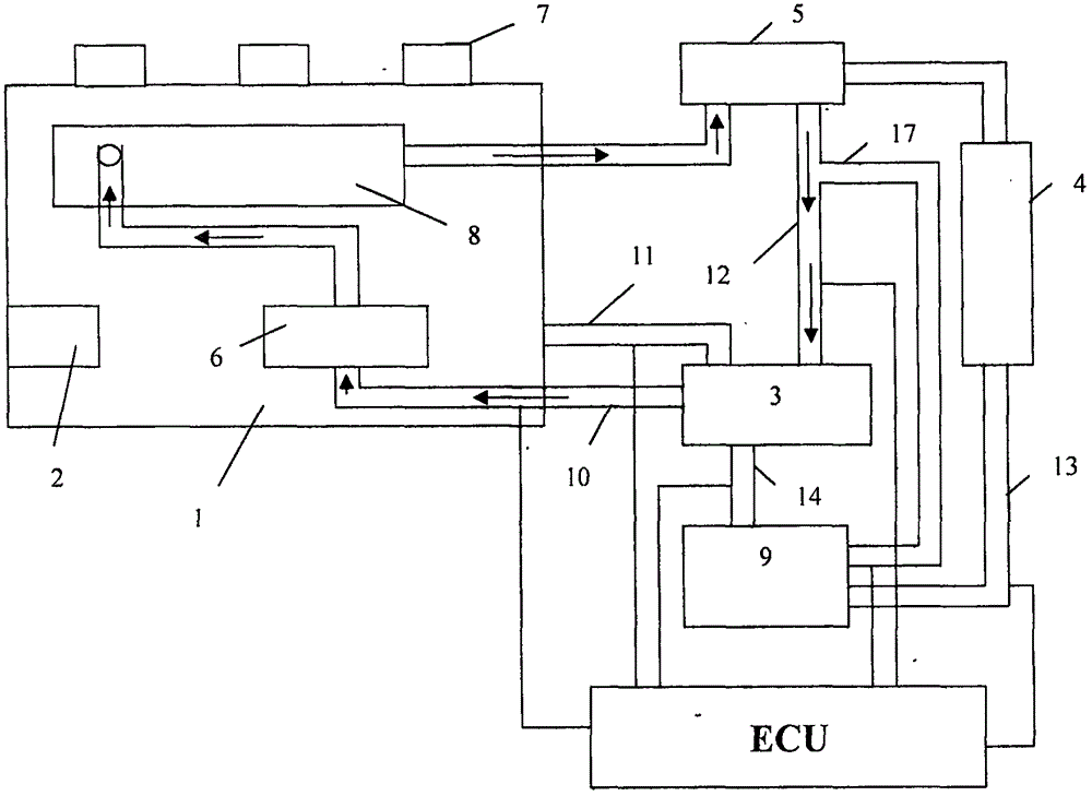
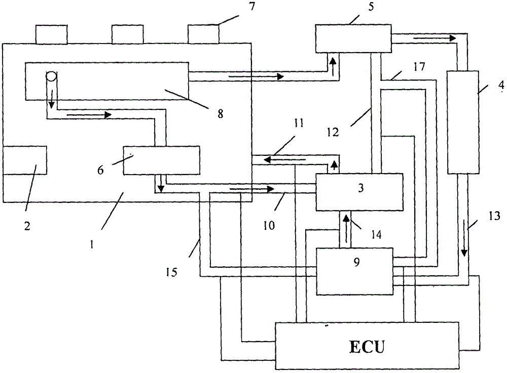
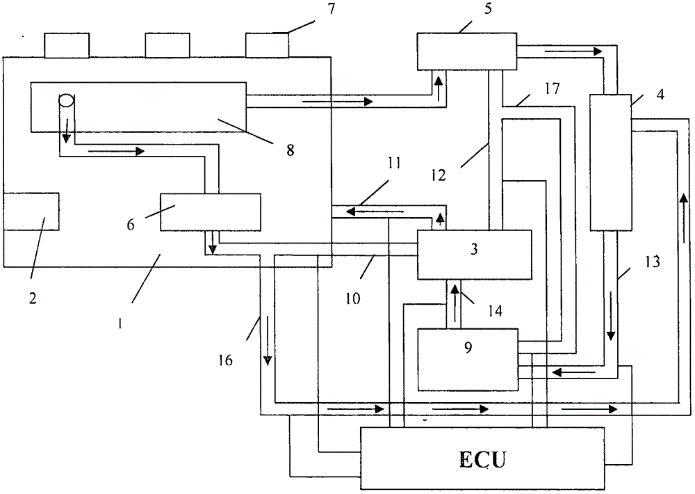
[0034] Figure 1-2 A schematic diagram of the water circulation system of the present invention is shown. The diesel engine body 1 is provided with a starter 2, and the starter 2 is an electric motor powered by a vehicle storage battery. The diesel engine 1 includes a cooling water circulation system, which includes a water pump 3, a thermostat 5, a radiator 4, and a conventional water tank 9. The water pump 3 extracts cooling water from the conventional water tank 9, and cools the internal circulation 8 of the engine body. The thermostat 5 and the radiator 4 dissipate heat, and enter the water tank again to complete a cooling cycle.

[0035] The water circulation system of the present invention also includes an auxiliary water tank 6...


PUM


Abstract

The invention provides a controlling method of an engine water cycle system. The water cycle system comprises a water pump, a conventional water tank, a vice water tank, a thermostat and a radiator. A water feeding pipe of the vice water tank communicates with the water pump, a water discharging pipe of the vice water tank communicates with a water discharging port of a loader body inner cycle air cylinder, and a loader body inner cycle water discharging pipe communicates with the thermostat; one way of a water discharging port of the thermostat communicates with the radiator, and one way of the water discharging port of the thermostat communicates with the water pump; a by-pass pipe arranged on a water discharging pipe of the thermostat is connected to the conventional water tank; the radiator communicates with the conventional water tank through a water discharging pipe, the conventional water tank communicates with the water pump through a water discharging pipe, and a loader body inner cycle communicates with the water pump through a water feeding pipe; and electromagnetic valves connected to an ECU are arranged on the water feeding pipe of the vice water tank, a loader body inner cycle water feeding pipe, the water discharging pipe of the conventional water tank, the water discharging pipe of the radiator, the by-pass pipe of the thermostat and the water discharging pipe of the thermostat correspondingly, and an electric preheater is arranged in the vice water tank. According to the controlling method, an engine can be preheated, the stability of the engine in the starting process is guaranteed, and the heat dissipation effect is also strengthened.

Description

technical field [0001] The invention relates to a water circulation method and system, in particular to a water circulation method and system for a loader engine. Background technique [0002] The engine water circulation system is usually used to cool the engine, and usually includes a water pump and a radiator. The water pump guides the cooling water in the water tank to the engine, absorbs the heat of the engine, and cools it in the radiator for the next cycle. However, there is usually only one water tank in the prior art, and there is a phenomenon of insufficient cooling water. At the same time, the heat dissipation area of ​​the radiator is limited, and the cooling water cannot be sufficiently cooled. [0003] In addition, the climate in northern my country is cold, and it is easy to freeze in winter, which makes it difficult to start the engine of the loader. Usually, when the engine is used in a low-temperature environment, due to the decrease in the evaporation, co...

Claims


Application Information

Patent Timeline
IPC IPC(8): F02N19/10F01P3/20F01P7/14F02B77/08
CPCF01P3/20F01P7/14F01P2007/146F02B77/089F02N19/10
Inventor 段文清
Owner 段文清
Learn More