
Fish inlet structure of fish passing facility

A fish passing facility and fish feeding technology, which is applied in water conservancy engineering equipment, water conservancy engineering, sea area engineering, etc., can solve the problems of unfavorable fish entry, failure to consider light, and inability to fully attract fish, so as to achieve the effect of improving fish luring effect

Active Publication Date: 2018-09-11
CHINA HYDROELECTRIC ENGINEERING CONSULTING GROUP CHENGDU RESEARCH HYDROELECTRIC INVESTIGATION DESIGN AND INSTITUTE
View PDF5 Cites 0 Cited by
  • Summary
  • Abstract
  • Description
  • Claims
  • Application Information

AI Technical Summary

Problems solved by technology

[0004] 1) The suction flow at the fish inlet of existing fish passing facilities usually comes from the flow of the fish passing facility itself. If the flow is not enough, water needs to be replenished to the fish inlet. For fish passing facilities with fishway structures, water is usually diverted from the upstream , but due to the problem of water head fluctuations, it is difficult to effectively control the flow rate of water replenishment; and for fish passing facilities such as fish elevators and fish collection, usually a pumping station is installed downstream to increase the diversion flow, but this method consumes a lot of energy. higher cost
[0005] 2) The fish inlet of the fish passing facility usually has only one opening, which cannot fully attract fish clustered in different directions around the fish inlet. Even though some fish inlets have multiple openings in different directions, the general direction of water replenishment is The only thing is that the replenishment water flow in other directions is not obvious, or it will generate certain turbulent flow, which is not conducive to fish entering
[0006] 3) Existing fish passing facilities generally only use water flow to attract fish, and fish inlets are generally made of non-transparent materials, without considering measures such as light and water flow to attract fish

Method used


Image

  • Fish inlet structure of fish passing facility
  • Fish inlet structure of fish passing facility
  • Fish inlet structure of fish passing facility

Examples


Embodiment Construction

[0023] The present invention will be further described below in conjunction with the accompanying drawings and specific embodiments.

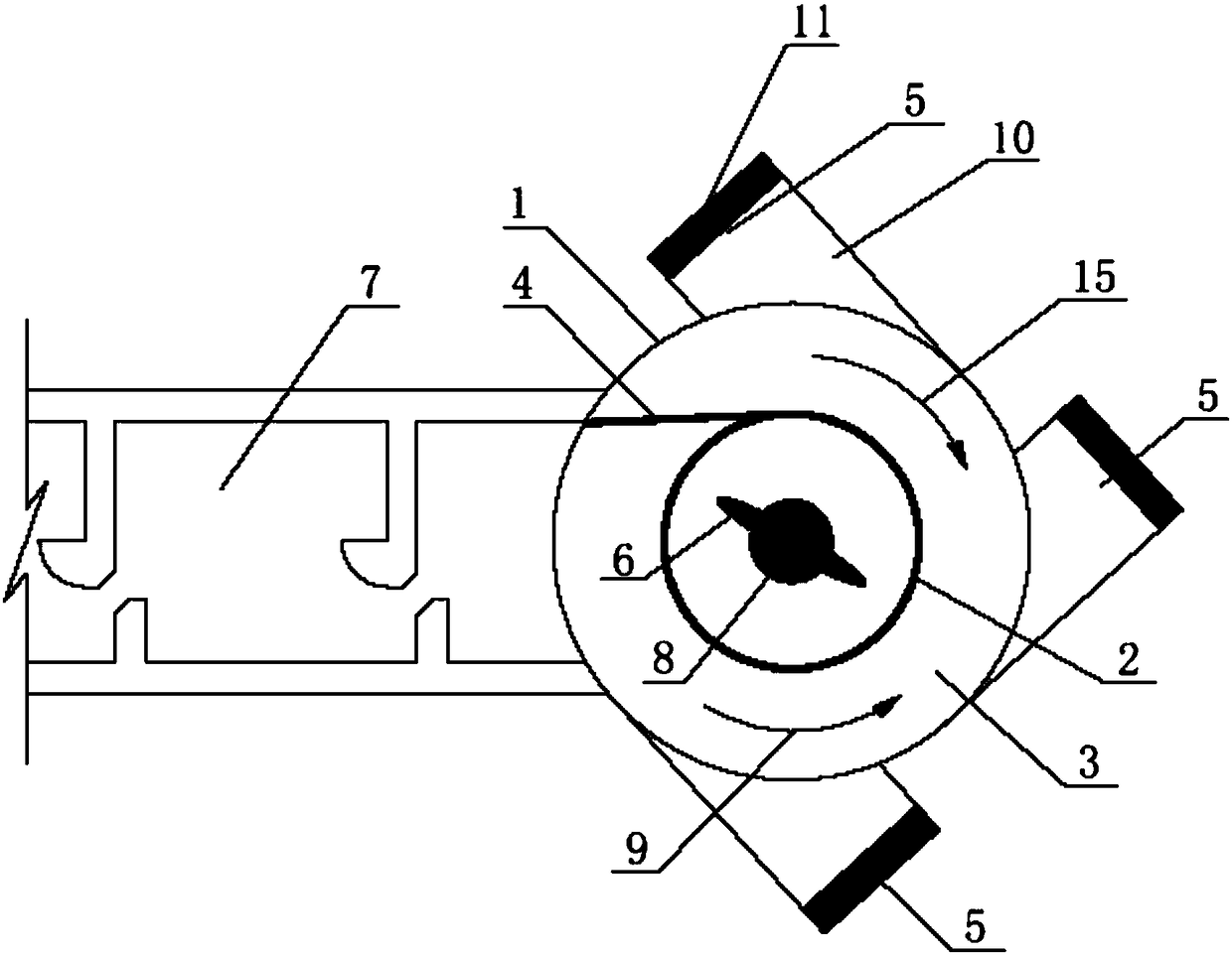
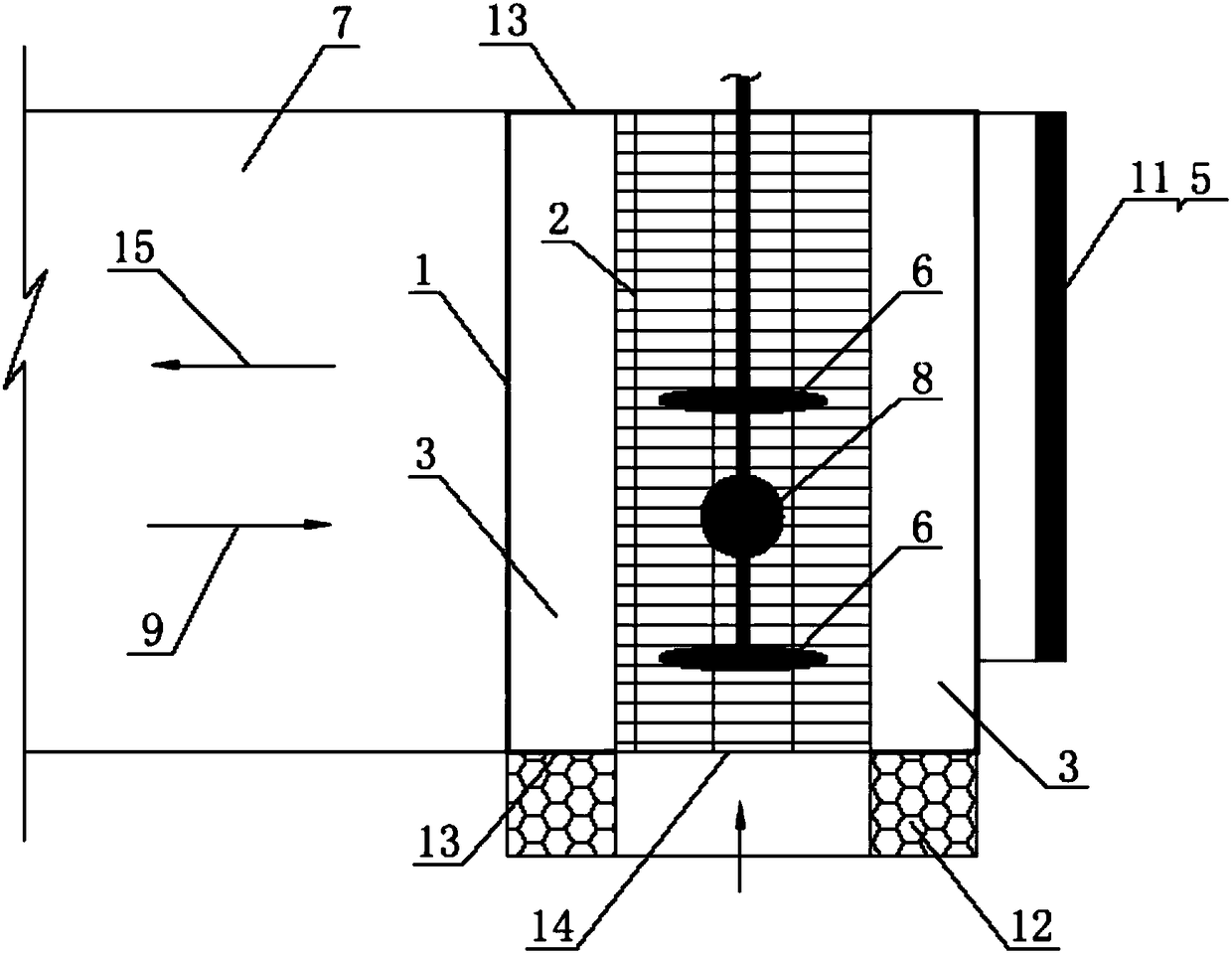
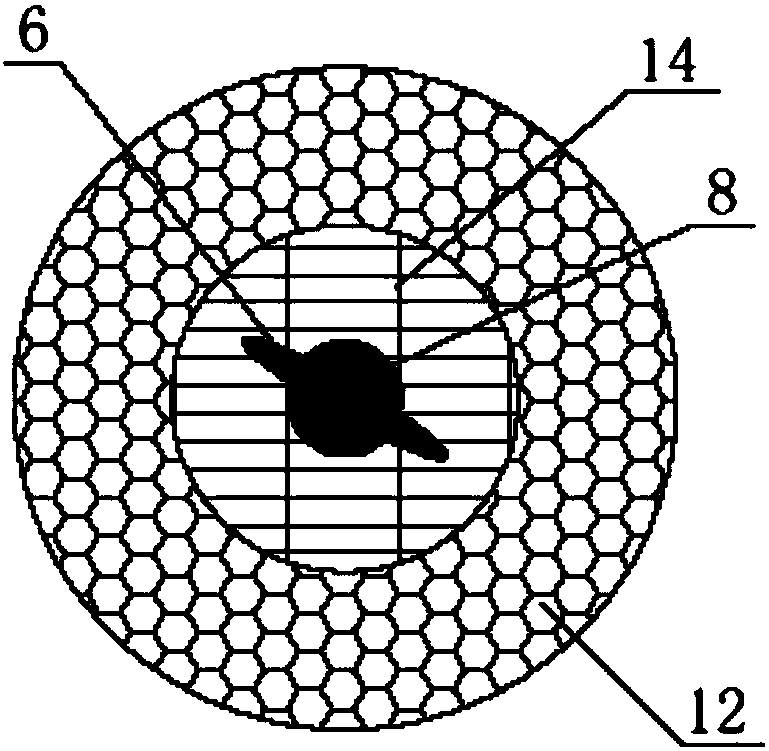
[0024] like Figure 1 to Figure 3 As shown in , the fish inlet structure of the fish passing facility according to the present invention, the fish inlet structure includes a cylindrical shell 1, a cylindrical fish fence 2 is arranged in the shell 1, and a cylindrical fish fence 2 is arranged in the shell 1. Between the fish grid 2 and the shell 1, an annular fish swimming channel 3 is formed. In the fish swimming channel 3, a partition fish barrier 4 is arranged to cut off the fish swimming channel 3 . One end of the fish swimming channel 3 passes through the shell 1 and communicates with the fish passing facility 7; a plurality of fish inlets 5 are arranged at intervals in the circumferential direction of the shell 1; a stirring mechanism 6 is arranged inside the cylindrical fish fence 2.

[0025] Wherein, the effect of stirring mechanism 6 i...


PUM


Abstract

The invention discloses a fish inlet structure for a fish passing facility and belongs to the field of hydropower engineering. The fish inlet structure which is capable of luring fish in multiple directions and used for the fish passing facility is provided and structurally comprises a cylindrical shell. A cylindrical fish screen is arranged in the shell. An annular fish passing path is formed between the cylindrical fish screen and the shell. A separation fish screen for separating the fish passing path is arranged in the fish passing path. One end of the fish passing path separated by the fish screen penetrates the shell and then communicates with the fish passing facility. Multiple fish inlets are formed in the peripheral direction of the shell at intervals. A stirring mechanism is arranged in the cylindrical fish screen. According to the fish inlet structure for the fish passing facility, the fish inlets distributed in the peripheral direction of the shell are formed, meanwhile water flow generated by stirring of the stirring mechanism can flow along the annular fish passing path, suction water flow in the fish inlet direction is formed at each fish inlet, and multi-direction fish luring is achieved at the same time in the peripheral direction of the shell.

Description

technical field [0001] The invention relates to the field of water conservancy and hydropower engineering, in particular to a fish inlet structure of a fish passing facility. Background technique [0002] In recent years, my country's hydropower project construction has entered a peak period, but the construction of hydropower gates and dams has separated the original fish into two groups, making it impossible for migration and genetic exchange, and weakening the viability of the population. In addition, under the trend of increasing attention from all walks of life to the protection of the ecological environment of hydropower projects, the environmental and ecological damage caused by the construction and operation of large-scale hydropower projects has become a hot spot of social concern, and the implementation of environmental and ecological protection measures has directly It is related to the overall image of the project, and even restricts the construction and operatio...

Claims


Application Information

Patent Timeline
Patent Type & Authority Patents(China)
IPC IPC(8): E02B8/08E02B1/00
CPCY02A40/60
Inventor 文典孙大东郎建吴迪康昭君
Owner CHINA HYDROELECTRIC ENGINEERING CONSULTING GROUP CHENGDU RESEARCH HYDROELECTRIC INVESTIGATION DESIGN AND INSTITUTE
Learn More