
leveler

A twist leveler and adjuster seat technology, applied in textiles and papermaking, etc., can solve the problems of difficult control of surface roughness, increased difficulty of guide wheel processing, large surface hardening treatment, etc., to achieve simple structure, strong twisting damage The effect of reduction and easy operation

Active Publication Date: 2019-04-09
YICHANG JINGWEI TEXTILE MACHINERY
View PDF7 Cites 0 Cited by
  • Summary
  • Abstract
  • Description
  • Claims
  • Application Information

AI Technical Summary

Problems solved by technology

There are protrusions on the outer wall of the set guide wheel (2) to separate the inner and outer yarns, but this structure increases the friction with the guide wheel, especially this structure makes the processing of the guide wheel more difficult
For example, the surface where the yarn passes needs to be hardened, and the groove structure brings great difficulty to the surface hardening treatment, and the hardness and surface roughness after Yinhua are difficult to control

Method used


Image

  • leveler
  • leveler
  • leveler

Examples


Embodiment Construction

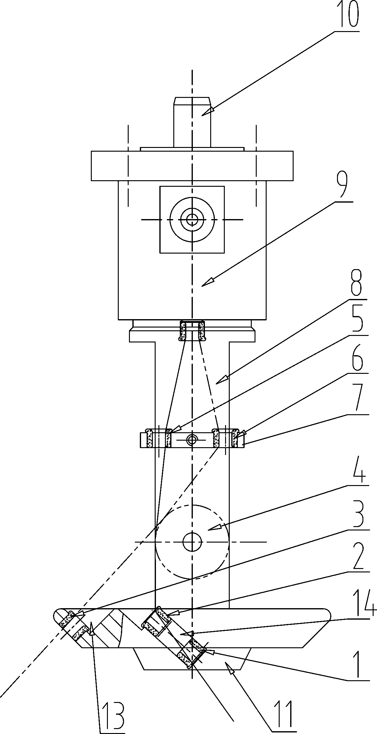
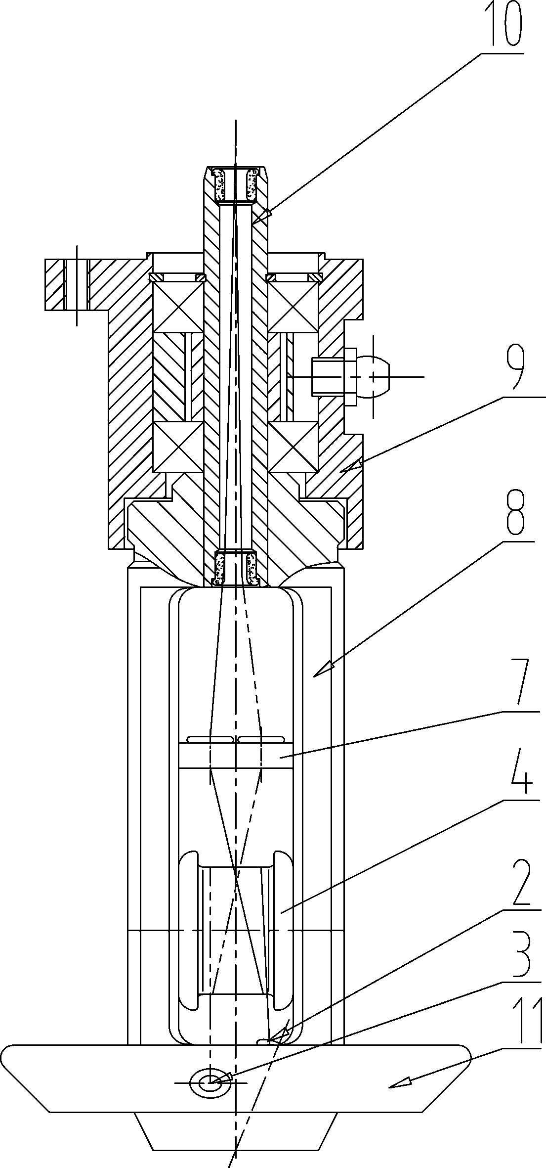
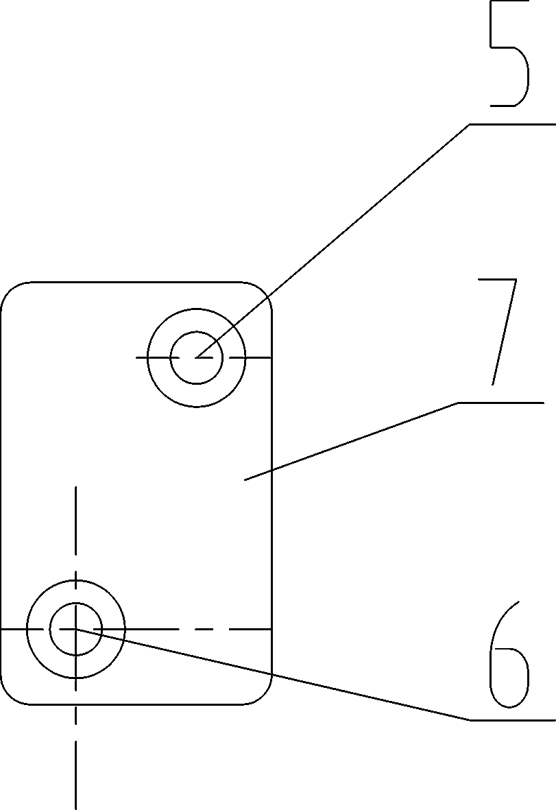
[0023] Such as Figure 1~4 Among them, a twist leveler includes a twist leveler frame 8, a balance plate 11 is provided at the bottom of the twist leveler frame 8, a combination roller 4 is arranged inside the twist leveler frame 8, and a yarn guide is fixed above the combination roller 4 plate 7, the fourth ceramic ring 5 and the fifth ceramic ring 6 which are independent of each other are arranged on the yarn guide plate 7. With this structure, the inner and outer yarns on the combination roller 4 are independent from each other and can not rub against each other. Simultaneously, the vibration of the ply yarn in the yarn guide tube 10 is reduced or eliminated.

[0024] The preferred solution is as figure 1 , 2 Among them, the yarn guide plate 7 is located in the hollow part inside the twist leveler frame 8, and the yarn guide plate 7 is arranged horizontally. The main effect of this solution is to reduce or eliminate the trembling of the ply yarn in the yarn guide tube 1...


PUM


Abstract

The invention provides an even twister. The even twister comprises an even twister frame, a balance plate is arranged at the bottom of the even twister frame, a combined roller is arranged in the even twister frame, a yarn guide plate is fixedly arranged above the combined roller, and a fourth ceramic ring and a fifth ceramic ring independent with each other are arranged on the yarn guide plate. When the yarn guide plate is arranged above the combined roller and two independent ceramic rings are arranged on the yarn guide plate, it is avoided that inner yarns and outer yarns wound around the surface of the combined roller are rubbed against each other, and accordingly the strength loss of twisting yarns is avoided. By arranging the yarn guide plate, the bending angle from the surface of the combined roller to a yarn guide pipe is reduced.

Description

technical field [0001] The invention relates to the field of twisters for spinning machine parts in textile machines, in particular to a twist leveler. Background technique [0002] There is an existing twister for twisting yarns. The publication number of the patent document is CN100552108C. The bobbin axis is coaxial with the balance disc, and the ceramic ring is arranged on the balance disc. A ceramic ring and a rotating combined roller are installed near the lower part of the gap in the middle of the rotor frame, and a ceramic ring is arranged on the end face. The combination roller is supported by a shaft installed in the rotor frame, and its axis is perpendicular to and intersects with the axis of the yarn guide tube, and the roller rotates around the shaft. The upper part of the rotor frame is connected with the yarn guiding tube, and the twisting rotor mechanism can flexibly rotate around the central axis of the rotor seat, and the structure is simple and easy to m...

Claims


Application Information

Patent Timeline
Patent Type & Authority Patents(China)
IPC IPC(8): D01H13/04D01H13/12
CPCD01H13/04D01H13/12
Inventor 汪斌刘文涛杨华明潘松吕昌法别佑廷
Owner YICHANG JINGWEI TEXTILE MACHINERY
Learn More