Dynamic bottom aeration system and aeration method thereof

An aeration system and aeration technology, applied in chemical instruments and methods, sustainable biological treatment, water/sludge/sewage treatment, etc., can solve problems such as high pipeline investment cost, increased re-investment, and increased infrastructure investment. Achieve the effects of saving operating costs, shortening the air supply pipeline, and saving investment costs

Pending Publication Date: 2017-03-22
HUATIAN ENG & TECH CORP MCC
View PDF9 Cites 5 Cited by
  • Summary
  • Abstract
  • Description
  • Claims
  • Application Information

AI Technical Summary

Problems solved by technology

[0004] In addition to the air supply system and aeration diffusion system, the conventional fixed installation bottom aeration system also needs to be equipped with a submersible push-flow mixer to achieve a better mixing effect; the air supply system requires a special blower room to protect the equipment from Dust and sound insulation, so the investment cost is high; and because of the use of long-distance gas pipelines, not only the pipeline investment cost is high, but also the pipeline loss is large, and energy waste is serious; more importantly, the aeration distributor (generally an aeration Aeration pan or aeration tube) is usually fixed and installed at the bottom of the oxidation ditch with a unit structure of several aerators. This aeration method is a static aeration mode, which has the following fatal flaws:
[0005] 1. The bottom aeration device needs to be equipped with blower equipment for centralized gas supply, so a blower room needs to be built to protect the blower equipment, which increases infrastructure investment;
[0006] 2. Centralized air supply must be supplemented by air supply pipelines. The longer the air supply pipeline, the greater the pipeline loss, that is, the higher the energy consumption, and the higher the pipeline auxiliary installation costs;
[0007] 3. The aeration and oxygenation of the bottom layer shows uneven aeration, some areas have high dissolved oxygen concentration, and some areas have low dissolved oxygen concentration;
[0008] 4. The diaphragm aerator is easy to block when the bottom aeration is used, and it decays year by year, so it needs to be cleaned and replaced regularly;
[0009] 5. Once the aerator is blocked or damaged, it needs to be replaced immediately, otherwise it will affect the aeration effect; when the aerator is cleaned and replaced, it needs to stop production and production, which will affect the normal production; the aerator needs to be replaced regularly due to attenuation, and the cycle will increase and then put into operation ;
[0010] 6. When the fan stops supplying air, the sludge at the bottom of the oxidation ditch will fill the aerator, which will easily cause the aerator to be blocked;
[0011] 7. The lower part of the fixedly installed aerator has become a dead angle, and the sludge is in a silted state. Once the machine is shut down, the sludge will bury the aerator. When it is started again, it needs to consume more energy to stir the sludge away.
[0012] The traditional fixed bottom aeration mode has been followed for decades, and the fatal flaw has not been broken through. People in the industry only continue to explore and update from the geometric shape of the aeration head and the material of the aeration diaphragm, but there is no way at all. Solve fatal flaws such as blind aeration areas and dead angles caused by fixed installations, resulting in suboptimal oxygen transmission effects

Method used


Image

  • Dynamic bottom aeration system and aeration method thereof
  • Dynamic bottom aeration system and aeration method thereof
  • Dynamic bottom aeration system and aeration method thereof

Examples


Embodiment Construction

[0034] In the following description, for purposes of explanation, numerous specific details are set forth in order to provide a thorough understanding of one or more embodiments. It may be evident, however, that these embodiments may be practiced without these specific details. In other instances, well-known structures and devices are shown in block diagram form in order to facilitate describing one or more embodiments.

[0035] Various embodiments according to the present invention will be described in detail below with reference to the accompanying drawings.

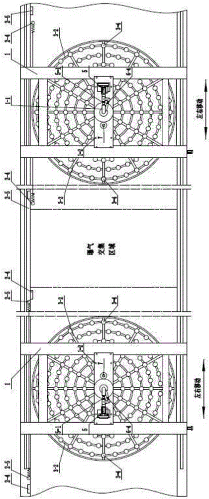
[0036] figure 1 It is a schematic front view of the dynamic bottom aeration system of the present invention, figure 2 It is a top view schematic diagram of the dynamic bottom aeration system of the present invention, such as figure 1 and figure 2 As shown, the dynamic bottom aeration system includes:

[0037] Two trusses 1 span the oxidation ditch 8, a bridge 1-1 is arranged between the two trusses 1, and the tw...


PUM


Abstract

The invention provides a dynamic bottom aeration system and an aeration method. The system comprises two trusses, a truss moving unit, an aeration component, a scraper, a fan, a blow-brushing unit and a second driving device, wherein a bridge is arranged between the two trusses; the truss moving unit comprises a guide rail, truss rollers, a first driving device and limiting devices; the first driving device drives the truss to move on the guide rail; the aeration component comprises an aeration air supply pipe, aeration air supply branch pipes, a fixed support and aerators; the aeration air supply branch pipes are radially connected on the aeration air supply pipe; the aerators are communicated with the aeration air supply branch pipes; the scraper is arranged below the fixed support; the fan is communicated with the aeration air supply pipe and a blow-brushing air supply pipe; the blow-brushing unit comprises the blow-brushing air supply pipe, a blow-brushing air supply branch pipe and air nozzles; the blow-brushing air supply pipe and the aeration air supply branch pipes are concentric; one end of the blow-brushing air supply pipe is communicated with an air outlet of the fan and the other end is connected with the blow-brushing air supply branch pipe; the blow-brushing air supply branch pipe is installed on the fixed support; the air nozzles are arranged on the blow-brushing air supply branch pipe; the second driving device drives the aeration component and the blow-brushing unit to rotate. The system has the advantage of no blind area and dead center dynamic aeration oxygenation.

Description

technical field [0001] The invention relates to the technical field of water treatment equipment, and more specifically, to a dynamic bottom aeration system and an aeration method thereof. Background technique [0002] The aeration process is the key process in the aerobic (denitrification) process section of sewage biological treatment. Through aeration, the sewage can obtain enough dissolved oxygen, and at the same time, it assists the submersible plug-flow mixing equipment to continuously mix and mix, so that the organic matter in the sewage and Microorganisms are in full contact with dissolved oxygen, and prevent activated sludge from sedimentation and sedimentation, so as to ensure that microorganisms can oxidize and decompose organic matter under the condition of sufficient dissolved oxygen, so as to eliminate BOD in sewage 5 the goal of. [0003] The commonly used aeration methods in the biological treatment aeration process of sewage treatment include completely mix...

Claims


Application Information

Patent Timeline
Patent Type & Authority Applications(China)
IPC IPC(8): C02F3/12
CPCC02F3/1257C02F3/1278Y02W10/10
Inventor 王月萍程寒飞詹茂华张鑫珩
Owner HUATIAN ENG & TECH CORP MCC
Why Eureka
Try Eureka