Eureka AIR delivers breakthrough ideas for toughest innovation challenges, trusted by R&D personnel around the world.

Sliding block and high-speed precise punch

A technology of precision punching and sliding block, used in presses, manufacturing tools, etc., can solve the problems of poor stamping product quality, lower die temperature, stamping product deformation, etc., to ensure the pass rate, solve the temperature rise, and improve production. The effect of efficiency

Inactive Publication Date: 2017-03-22
浙江帅锋精密机械制造有限公司
View PDF10 Cites 0 Cited by
  • Summary
  • Abstract
  • Description
  • Claims
  • Application Information

AI Technical Summary

Problems solved by technology

[0004] In order to solve the problem of deformation of stamping products due to the temperature rise of the punch in the upper die during the operation of the above-mentioned high-speed precision punching machine, it is considered to refit the slider directly connected to the upper die, so that the improved slider has the ability to realize self-cooling and cooling. structure, thereby reducing the temperature of the upper mold directly fixedly connected with the slider, avoiding the problem of poor quality and low precision of stamping products caused by the temperature rise of the punch inside the upper mold

Method used


Image

  • Sliding block and high-speed precise punch
  • Sliding block and high-speed precise punch
  • Sliding block and high-speed precise punch

Examples


Embodiment Construction

[0015] In order to make the object, technical solution and advantages of the present invention clearer, the present invention will be further described in detail below in conjunction with the accompanying drawings and embodiments. It should be understood that the specific embodiments described here are only used to explain the present invention, not to limit the present invention.

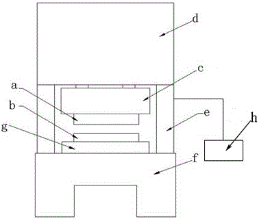
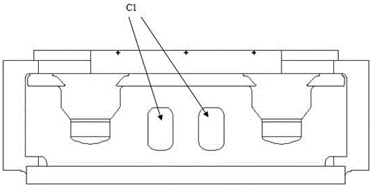
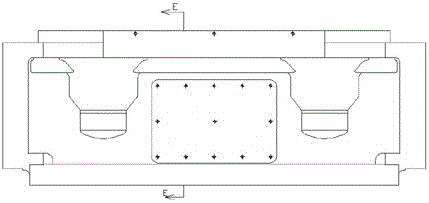
[0016] Such as figure 1 Shown is a schematic diagram of the overall structure of the high-speed precision punching machine according to the present invention, which includes a top seat d, a middle body e and a base f, and a slider c and a workbench g are arranged in the middle body e, and a slider c is set on the slider c. There is a through hole c1, the mold is set between the slider c and the worktable g, the mold includes an upper mold a and a lower mold b, the upper mold a and the slider c are fixedly connected, and the lower mold b is fixed on the worktable g. After the punching machine is in...


PUM


Abstract

The invention provides a sliding block and a high-speed precise punch. A cavity is formed in the sliding block. The front side and the back side of the sliding block are provided with through holes communicating with the cavity. The front side of the sliding block is provided with a first baffle covering the corresponding through hole. The back side of the sliding block is provided with a second baffle covering the corresponding through hole. A cooling liquid storage area is formed through the first baffle, the second baffle and the cavity. A cooling liquid inlet is formed in the upper portion of the second baffle. A cooling liquid outlet is formed in the lower portion of the second baffle. The high-speed precise punch comprises a top base, a middle table body and a bottom base. The sliding block is arranged on the upper portion in the middle table body. A workbench is arranged on the lower portion in the middle table body. A die comprising an upper die body and a lower die body is arranged between the sliding block and the workbench. According to the sliding block and the high-speed precise punch, the temperature of the upper die body connected with the sliding block is decreased by cooling the sliding block, the problem that due to the fact that the temperature of the upper die body is increased, a punched product is unqualified is solved, and the production efficiency is greatly improved.

Description

technical field [0001] The invention relates to a slider and a high-speed precision punching machine. Background technique [0002] In the current mechanical punch structure, the slider is an essential and important moving part, which is not only the executive part of the punching reciprocating motion, but also the upper workbench where the punching die is installed. When the punching machine is working, the upper mold of the mold is first fixed on the slider, and the lower mold of the mold is fixed on the workbench; the punch is installed in the upper mold of the mold, and the die is installed in the lower mold of the mold; start the punch, The lower mold and the worktable of the mold are fixed, and the slider drives the upper mold of the mold to reciprocate. At the same time, the stamping material is fed into the mold through the feeder, and the stamping is realized under the action of the concave and convex mold. [0003] In actual production, in order to reduce producti...

Claims


Application Information

Patent Timeline
IPC IPC(8): B30B15/00B30B15/34
CPCB30B15/00B30B15/34
Inventor 张治军彭进利李建锋吴晓婷汪吉东刘金奎
Owner 浙江帅锋精密机械制造有限公司
Why Eureka
Eureka Blog
Learn More