Portable insect trap

An insect trap, portable technology, used in devices for catching or killing insects, animal husbandry, applications, etc., can solve the problems of error prone, forgetting the number of insects, mixing insects, etc.

Active Publication Date: 2017-03-22
HENAN UNIVERSITY OF TECHNOLOGY
View PDF5 Cites 7 Cited by
  • Summary
  • Abstract
  • Description
  • Claims
  • Application Information

AI Technical Summary

Problems solved by technology

[0003] (1) Although the electric insect sucker can hold insects in hand, because the shape of the electric insect sucker is gun-shaped, the alignment of the flukes is not high, and the efficiency of suction is not high because the insects move very fast;
[0004] (2) In the insect research laboratory, sometimes the quantity of the insects to be studied is also required. This electric insect sucker in the prior art needs personnel to memorize the quantity when inhaling the insects. Quantity, which is easy to make mistakes;
[0005] (3) In the insect research experiment, it is necessary to catch different kinds of insects for research. When catching different kinds of insects, the electric insect sucker in the prior art needs to change the insect inlet tube and the insect storage tube back and forth. In the process, sometimes insects have already escaped and need to be rediscovered, which greatly reduces the efficiency of insect catching;
[0006] (4) And if the switch of the electric insect sucker in the prior art is turned on, the fan will work all the time, and it is easy to inhale some unnecessary insects, so that the insects are mixed together, and personnel are required to sort them later, resulting in low efficiency of catching insects

Method used


Image

  • Portable insect trap
  • Portable insect trap
  • Portable insect trap

Examples


Embodiment 1

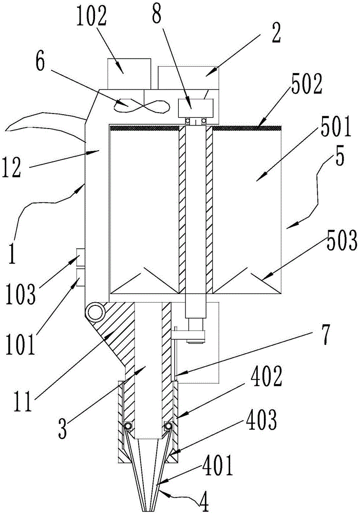
[0037] Such as figure 1The structure schematic diagram of the first embodiment of the portable insect trap shown includes a housing 1, the upper end of the housing 1 is provided with a power supply 2, and the housing 1 is provided with an insect inlet channel 3 extending from bottom to top, and the housing 1 The lower end of the lower end is provided with a suction insect head 4 which communicates with the insect passage 3, and the caliber is adjustable. In the housing 1, an insect collecting bin 5 is installed above the insect entering passage 3, and the insect collecting bin 5 is provided with a set The blower fan 6 of negative pressure is formed in the worm bin 5.

[0038] Further preferably, the insect collecting bin 5 is rotatably assembled on the casing 1 and is composed of at least two insect collecting cavities 501 arranged along the circumferential direction.

[0039] Further preferably, the insect-collecting chamber 501 has a structure with upper and lower openings,...

Embodiment 2

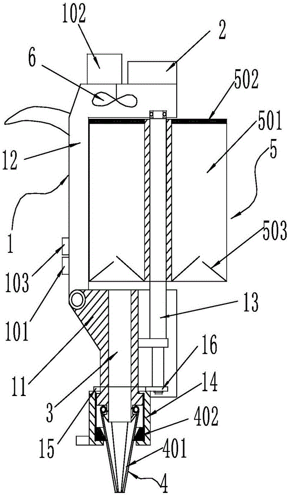
[0051] Such as figure 2 As shown, the difference between this embodiment and the first embodiment is that the way of linkage between the fluke head and the insect collection bin is different, and the linkage between the fluke head and the insect collection bin in the second embodiment is realized through the following structure.

[0052] A linkage mechanism is arranged between the sucker head and the insect collection bin, and the linkage mechanism includes a connecting rod 13 fixedly connected with the insect collection bin 5 and a rotating block 14 rotatably assembled at the lower end of the housing 1, and the adjusting block 402 is threadedly assembled on the rotating block. 14, and the adjustment block 402 moves up and down to fit on the outer peripheral surface of the disc, the upper end surface of the rotating block 14 is fixedly provided with the first gear 15, the lower end of the connecting rod 13 is fixedly provided with the second gear 16, the first gear 15 is enga...

Embodiment 3

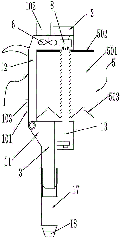
[0058] Such as image 3 As shown, the difference between the present embodiment and the first embodiment lies in that the structure of the fluke head with adjustable caliber is different, and the linkage between the fluke head and the insect collecting bin in this embodiment is realized through the controller. The sucker head of the portable insect trap of this embodiment includes a sucker head body 17 and a hole adjustment assembly 18, and the sucker head body 17 is provided with an insect inlet through hole extending from bottom to top along its center line, and the hole adjustment assembly is arranged on the insect inlet bottom of the through hole. Such as Figure 4 As shown, the hole adjustment assembly 18 includes a movable ring 181 and a fixed ring 182 that are coaxially arranged on the upper and lower sides and relatively rotated. The cloth is provided with a movable pin slot 184 corresponding to the fixed pin hole 183 and extending radially along the movable ring 181...


PUM


Abstract

The invention discloses a portable insect trap which comprises a shell and a power supply arranged at the upper end of the shell. An insect inlet channel is arranged inside the shell. The lower end of the shell is provided with an insect suction head which is communicated with the insect inlet channel, wherein the calibers of the insect suction head are adjustable. An insect collection bin is assembled at the upper end of the insect inlet channel on the shell. The insect collection bin is communicated with the insect inlet channel when in use and is closed when in standby. A fan is arranged above the insect collection bin. The insect collection bin is rotationally assembled on the shell and is composed of at least two insect collection cavities distributed in the circumferential direction. The insect collection bin and the insect suction head are arranged in a linkage mode so that the insect collection cavities can correspond to the calibers of the insect suction head one to one respectively. According to the portable insect trap, the calibers of the insect suction head can be adjusted so as to adapt to catching of insects of different sizes, the replacement speed is high, and the insect catching efficiency is greatly improved. The adjusted calibers of the insect suction head are automatically matched to corresponding insect collection cavities, different insects can be automatically and precisely classified, and the insect catching efficiency is further improved.

Description

technical field [0001] The invention relates to a device for catching insects, in particular to a portable insect catcher. Background technique [0002] In daily life and work, especially in the laboratory, it is necessary to study some habits of insects and their own characteristics, so collecting insect samples is a key link. In the process of collecting insects, the survival rate of insects should be guaranteed. The current existing electric insect trap structure is the patent document named "electric insect sucker" disclosed by the application number 201520202809.2. This patent document discloses an electric insect sucker, which includes an electric suction device and an insect collecting device. The electric air suction device includes a gun-shaped housing, in which a motor is installed, and fan blades are fixed on the output shaft of the motor. A battery is installed inside the handle of the gun-shaped housing, and a power interface for charging the battery is provid...

Claims


Application Information

Patent Timeline
IPC IPC(8): A01M5/08
CPCA01M5/08Y02A50/30
Inventor 李慧
Owner HENAN UNIVERSITY OF TECHNOLOGY
Why Eureka
Try Eureka