Transformer for test

A technology for transformers and tests, applied in the direction of transformers, variable transformers, transformer/inductor cores, etc., can solve the problems of difficult adjustment and difficult operation of transformers, and achieve convenient use, convenient electromagnetic coupling needs, and reduced costs Effect

Active Publication Date: 2018-04-10
WOLONG ELECTRIC GRP CO LTD +1
View PDF6 Cites 0 Cited by
  • Summary
  • Abstract
  • Description
  • Claims
  • Application Information

AI Technical Summary

Problems solved by technology

[0004] The problem to be solved by the present invention is to provide a test transformer, so that the existing test transformers are difficult to operate and difficult to adjust.

Method used


Image

  • Transformer for test
  • Transformer for test
  • Transformer for test

Examples


Embodiment

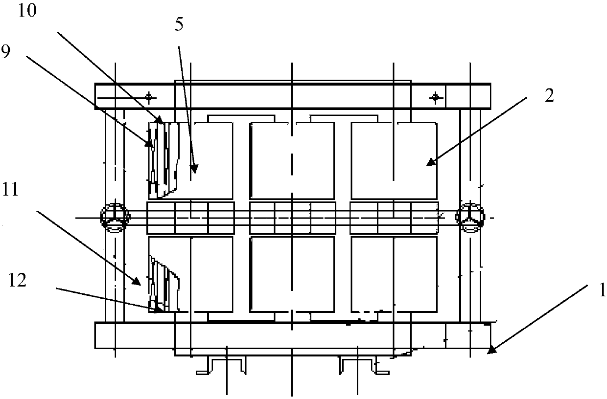
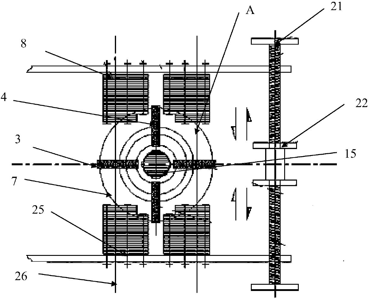
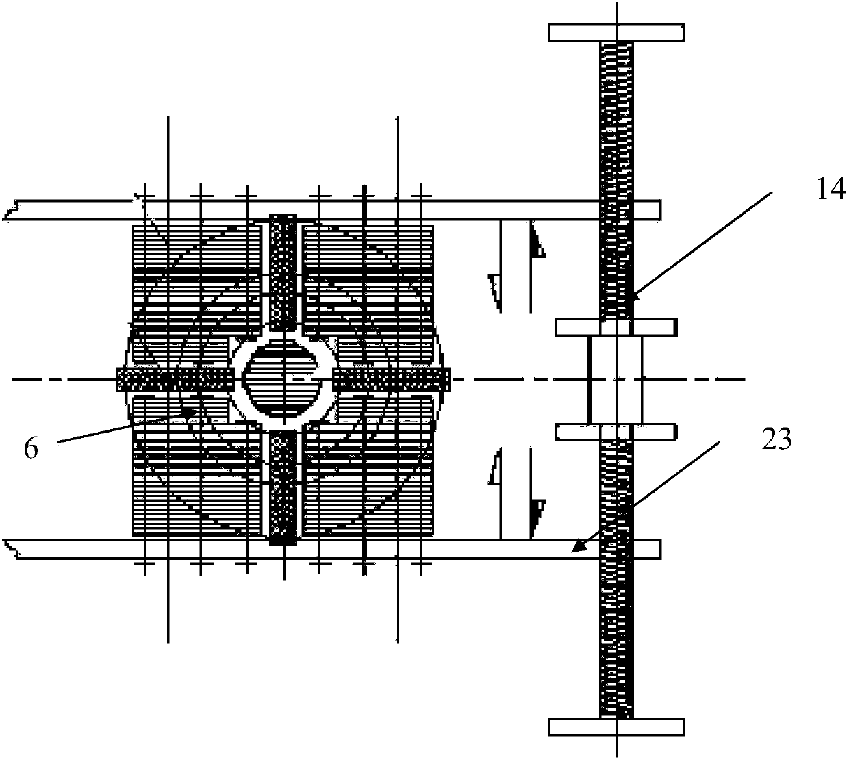
[0024] Embodiment: the present invention also discloses a kind of test transformer (see attached figure 1 , 2 , 3), including: support 1, iron core 5 groups 2 and phase electromagnetic coupling assembly 6; said iron core 5 groups 2 are installed on the support 1; said iron core 5 groups 2 include a plurality of iron cores 5; said The middle part of the iron core 5 has a pair of first insulating spacers 3 arranged along the length direction of the transformer and a pair of second insulating spacers 4 arranged along the width direction of the transformer; a pair of first insulating spacers 3 and a pair of second insulating spacers The insulating pads 4 intersect to form insulating groups 7 arranged in a cross shape;

[0025] The phase electromagnetic coupling assembly 6 includes a phase electromagnetic coupling iron core 15 and four groups of laminations 8; the phase electromagnetic coupling iron core 15 is arranged at the center of the cross-shaped insulating group 7; the four...


PUM


Abstract

The invention discloses a testing transformer. The testing transformer comprises a bracket, an iron core group and a phase electromagnetic coupling assembly, wherein the iron core group comprises multiple iron cores; a pair of first insulation cushion blocks which are arranged in the length direction of the transformer and a pair of second insulation cushion blocks which are arranged in the width direction of the transformer are arranged in the middle part of each iron core; the pair of the first insulation cushion blocks and the pair of the second insulation cushion blocks are crossed to form a cross-shaped insulating group; the phase electromagnetic coupling assembly comprises a phase electromagnetic coupling iron core and four groups of lamination sheets; the phase electromagnetic coupling iron core is arranged in the center of the insulating group; the four groups of lamination sheets are arranged on the periphery of the phase electromagnetic coupling iron core and positioned in four quadrants isolated by the cross-shaped insulating group; the four groups of lamination sheets are fixed on a pair of insulating plates; the two ends of the pair of the insulating plates are movably connected with a pair of parallel fixed rods in parallel; and the insulating plates can move along the fixed rods. According to the testing transformer, the coupling between upper and lower windings can be changed by setting that the lamination sheets slide along the fixed rods along with the insulating plates, so that the testing transformer is simple to operate and convenient to use in a test.

Description

technical field [0001] The invention relates to the field of transformer manufacturing, in particular to a test transformer. Background technique [0002] China's high-speed rail technology, from the early introduction of technology to the current independent research and development, China's high-speed rail technology has been continuously improved and improved, leading the world. At present, the speed of China's high-speed rail has exceeded 380 kilometers per hour, ranking at the world's leading level. The traction equipment of high-speed rail locomotives is high-precision and high-reliability equipment. However, the technical problems of high-speed rail still exist, mainly manifested in the powerful power, low energy consumption, high efficiency, and low-carbon environmental protection. This is a pair of contradictions. At present This is a difficult problem for all countries in the world, and it is also an eternal theme, especially the traction equipment of high-speed ra...

Claims


Application Information

Patent Timeline
Patent Type & Authority Patents(China)
IPC IPC(8): H01F29/12H01F27/26H01F27/245H02P13/10G01R31/00
CPCG01R31/00H01F27/245H01F27/266H01F29/12H02P13/10
Inventor 周华贾冰冰王百升
Owner WOLONG ELECTRIC GRP CO LTD
Why Eureka
Try Eureka