Eureka AIR delivers breakthrough ideas for toughest innovation challenges, trusted by R&D personnel around the world.

Heat pump system with fuel gas as heat source

A heat pump system and gas technology, applied in the field of heat pumps, can solve the problems of environmental pollution, poor heating effect, and low cost of use

Pending Publication Date: 2017-03-15
GREE ELECTRIC APPLIANCES INC
View PDF15 Cites 1 Cited by
  • Summary
  • Abstract
  • Description
  • Claims
  • Application Information

AI Technical Summary

Problems solved by technology

[0003] Based on this, in order to solve the problems of low heat exchange efficiency, poor heating effect, high cost, and environmental pollution in traditional heating methods, a new heating system with high heat exchange efficiency, good heating effect, low environmental pollution and low cost of use is provided. Heat pump system using gas as heat source

Method used


Image

  • Heat pump system with fuel gas as heat source

Examples


Embodiment Construction

[0028] In order to make the purpose, technical solution and advantages of the present invention clearer, the heat pump system using gas as the heat source of the present invention will be further described in detail through the following embodiments and in conjunction with the accompanying drawings. It should be understood that the specific embodiments described here are only used to explain the present invention, not to limit the present invention.

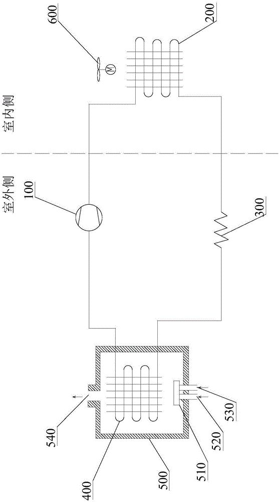
[0029] Such as figure 1 As shown, the embodiment of the present invention provides a heat pump system using gas as a heat source, including: a refrigerant circuit connected in sequence by a compressor 100, an indoor heat exchanger 200, a throttling device 300 and an outdoor heat exchanger 400, and The gas combustion chamber 500 ; the outdoor heat exchanger 400 is arranged in the gas combustion chamber 500 , and is used for exchanging heat with the high-temperature gas generated after the gas combustion in the gas combustion chamb...


PUM


Abstract

The invention relates to the technical field of heat pumps, in particular to a heat pump system with a fuel gas as a heat source. The heat pump system comprises a refrigerant loop and a fuel gas combustion chamber, wherein the refrigerant loop is communicated via a compressor, an indoor heat exchanger, a throttling device and an outdoor heat exchanger in sequence; the outdoor heat exchanger is arranged inside the fuel gas combustion chamber and is used for exchanging heat with a high-temperature gas generated after the fuel gas is combusted inside the fuel gas combustion chamber. According to the heat pump system, the fuel gas is adopted as the heat source, the heat of the combusting fuel gas can be exchanged with that of the outdoor heat exchanger; meanwhile, the outdoor heat exchanger is arranged in a relatively sealed high-temperature gas environment, and sufficient heat exchange can be achieved, so that nearly all heat of the combusting fuel gas can be transferred into a room, and thus indoor heating can be achieved; the heat pump system is high in fuel gas utilization rate and good in heating effect; the outdoor heat exchanger is arranged inside the fuel gas combustion chamber and is not frosted, so that the heat exchange effect can be ensured, and the heat pump system is not constrained by a low-temperature environment.

Description

technical field [0001] The invention relates to the technical field of heat pumps, in particular to a heat pump system using gas as a heat source. Background technique [0002] When heating in winter in cold and low temperature areas in the north, the following methods are generally adopted: coal-fired heating, electric heating for heating, wall-hung boiler heating, air source heat pump heating or water source, ground source heat pump heating, but the above methods have defects: coal-fired heating, Serious pollution; heating with electric heating, high power cost, poor heating effect, and poor economy; heating with wall-hung boilers, low heat transfer efficiency, and poor heating effect; heating with air source heat pumps, poor heating effect Frosting; water source, ground source heat pump heating, complex installation, high cost, and more limited installation locations. Contents of the invention [0003] Based on this, in order to solve the problems of low heat exchange ...

Claims


Application Information

Patent Timeline
Patent Type & Authority Applications(China)
IPC IPC(8): F24F5/00F24F11/02
CPCF24F5/001F24F2203/021F24F2221/34F24F11/89
Inventor 赵亮李志强李毛古容宗杰郭亚会彭斌简卓豪王亚楠李彬
Owner GREE ELECTRIC APPLIANCES INC
Why Eureka
Eureka Blog
Learn More