Fabricated type concrete foundation and installation method thereof

A concrete and prefabricated technology, applied in the direction of basic structure engineering, construction, etc., can solve the problems of aggravating frost heaving and thawing of the permafrost foundation of transmission lines, affecting the safe operation of transmission lines, and damaging bolts and threads, etc., so as to improve the strength and Freeze resistance, simple structure, and strength-enhancing effect

Active Publication Date: 2017-03-15
STATE GRID JIANGSU ECONOMIC RES INST +3
View PDF10 Cites 1 Cited by
  • Summary
  • Abstract
  • Description
  • Claims
  • Application Information

AI Technical Summary

Problems solved by technology

The installation needs to be hoisted by a crane. After the bolts are aligned with the bolt holes, the bottom plate is seated on the chassis. When aligning, all the bolts and bolt holes must be aligned at the same time. This is a time-consuming and laborious work, and the weight of the bottom plate is heavy. If you are not careful, you may be crushed and damaged, and at the same time, the bolt thread may be damaged when the bottom plate falls
[0005] At the same time, the construction of prefabricated concrete foundations in permafrost areas (such as the Qinghai-Tibet Plateau) will accelerate the degradation of permafrost due to climate warming and engineering effects, and aggravate the problems of frost heaving and thawing of permafrost foundations on transmission lines, which will seriously affect power transmission. Safe operation of the line

Method used


Image

  • Fabricated type concrete foundation and installation method thereof
  • Fabricated type concrete foundation and installation method thereof
  • Fabricated type concrete foundation and installation method thereof

Examples


Embodiment Construction

[0026] The present invention will be described in detail below in conjunction with the accompanying drawings.

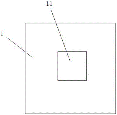
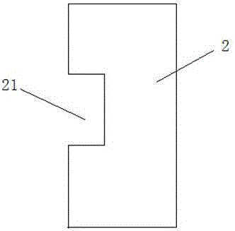
[0027] Such as figure 1 As shown, the concrete prefabricated foundation of the present invention includes a chassis 1 , two bottom plates 2 with the same size and shape, and foundation columns 3 . The chassis 1 and the foundation column 3 are respectively fixed to the bottom plate 2 by bolts.

[0028] combine Figure 2 to Figure 4 , The center of the chassis 1 is provided with a square bump 11 . A notch 21 is provided at the center of one side of the bottom plate 2; two bottom plates 2 are spliced ​​together, and the protrusion 11 of the chassis 1 is stuck in the spliced ​​notch 21, and the bottom plate 2 and the chassis 1 are fixed by bolts. The foundation column 3 includes a hollow cylinder 31 at the lower end and a truncated cone 32 at the upper end. The foundation column 3 is sleeved on the protrusion of the chassis through the hollow cylinder 31 at the lower...


PUM


Abstract

The invention discloses a fabricated type concrete foundation and an installation method of the fabricated type concrete foundation. The fabricated type concrete foundation comprises a base, two base boards and a foundation stand column. A convex block is arranged at the center of the base. The convex block is in a regular polygon shape. The center of one side of each base board is provided with a notch. The two base boards are spliced and fixed to the upper end of the base through bolts. The shape of the two spliced base boards is matched with that of the base. The shape of the spliced notches is matched with that of the convex block of the base. The lower end of the foundation stand column is a hollow cylinder. The foundation stand column is arranged on the convex block of the base in a sleeved manner through the hollow cylinder located at the lower end of the foundation stand column and fixed to the base boards through bolts. The inner circle of the hollow cylinder is externally tangent to the convex block. A pouring hole is formed in the hollow cylinder and communicates with the hollow portion inside the hollow cylinder. According to the fabricated type concrete foundation, the base boards and the foundation stand column are located through the convex block arranged at the center of the base, all the bolts are convenient to align at the same time, installation is more convenient and accurate, and the damage to screw threads of the bolts is avoided.

Description

technical field [0001] The invention relates to an assembled foundation, in particular to a concrete assembled foundation. Background technique [0002] Prefabricated foundation, also known as prefabricated foundation, is a basic form of factory prefabrication and on-site assembly. Compared with the cast-in-place concrete foundation, it saves 30-50% of the labor force, shortens the construction period by 1 / 3-1 / 2, and the quality of the foundation processing is guaranteed (the processing conditions in the factory are good), and the construction operation is less affected by the seasonal climate, which is conducive to mechanization Or semi-mechanized operations, reducing the work intensity of construction personnel, is the development direction of transmission line foundation construction. [0003] Prefabricated foundations are divided into metal foundations and concrete prefabricated foundations according to different materials. Although the metal foundation is convenient f...

Claims


Application Information

Patent Timeline
Patent Type & Authority Applications(China)
IPC IPC(8): E02D27/42E02D27/35
CPCE02D27/35E02D27/42E02D2300/002
Inventor 张军安增军王庭华吴雪王波卢璐戴亚崔厚坤李伯颐
Owner STATE GRID JIANGSU ECONOMIC RES INST
Why Eureka
Try Eureka