
Sludge drying air source heat pump system and sludge drying machine thereof

A sludge drying and heat pump technology, applied in water/sludge/sewage treatment, dryer, dehydration/drying/thickened sludge treatment, etc., can solve the problems of large energy consumption, a large amount of heat, and high cost, and achieve reduction The effect of small heat loss and reduction of energy waste

Active Publication Date: 2017-03-15
天津五洲同创空调制冷设备有限公司
View PDF3 Cites 2 Cited by
  • Summary
  • Abstract
  • Description
  • Claims
  • Application Information

AI Technical Summary

Problems solved by technology

[0006] The disadvantage of this patent is that in the process of drying sludge, a large amount of hot and humid air will be discharged, so it is necessary to supplement natural wind and hot air all the time to maintain the working temperature in the box
However, when the hot air is heated to a temperature that can maintain the cabin at the working temperature, a large amount of heat is required, that is, a large amount of energy is consumed.
Lead to low energy efficiency and high cost

Method used


Image

  • Sludge drying air source heat pump system and sludge drying machine thereof
  • Sludge drying air source heat pump system and sludge drying machine thereof
  • Sludge drying air source heat pump system and sludge drying machine thereof

Examples


Embodiment 2

[0051] Such as Figure 4 As shown, a sludge drying air source heat pump system includes Embodiment 1, and also includes a mixer 25 for mixing dry sludge and wet sludge, and a mixer for granulating the semi-dry sludge discharged from the mixer 25. A granulator 26 and a sieving machine 27 for sieving sludge granules. The discharge port of the mixer 25 is connected with the feed port of the granulator 26 through a hoist 31 . The discharge port of the granulator 26 and the feed port of the sieving machine 27 are also connected by a hoist 31 .

[0052] Such as Figure 4 As shown, the sieving machine 27 is a three-stage grading sieve, which can sieve the sludge particles according to their size. The screening machine 27 is provided with a first discharge port 28 for discharging small sludge particles, a second discharge port 29 for discharging large sludge particles and a third discharge port for discharging sludge powder. port 30, the first discharge port 28 is connected with t...


PUM


Abstract

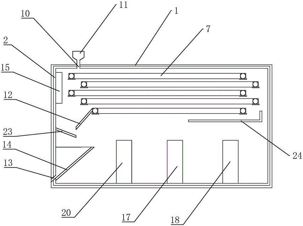
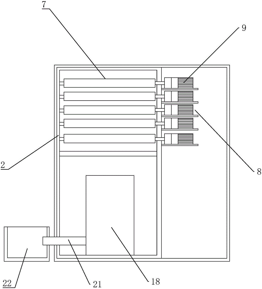
The invention discloses a sludge drying machine which comprises a compartment, wherein the compartment is internally provided with a conveyer belt for conveying sludge; a feeding hole and a discharge hole are respectively formed in the upper end and the lower end of the compartment; the compartment is arranged in a sealed manner; a guide fan for driving air to form a heat stream is arranged at one end opposite to the feeding hole, of the conveyer belt; a heating part for heating the air is arranged at one end close to the guide fan, at the lower end of the conveyer belt; an evaporator for recycling wastewater in hot and damp air is arranged at one end far away from the guide fan, at the lower end of the conveyer belt; a partitioning plate for guiding the heat stream to flow to the evaporator is arranged on one side back to the guide fan, on the inner wall of the compartment; a water discharge tube is connected with a liquid outlet of the evaporator; a diversion fan for leading the heat stream to the heating part from the evaporator is arranged between the evaporator and the heating part. As the compartment is sealed, the air flow forms sealed heat circulation inside the compartment, as much heat as possible can be adopted to dry sludge, instead of being discharged into the air directly to cause heat loss, and thus the energy utilization rate can be increased.

Description

technical field [0001] The invention relates to sludge treatment equipment, in particular to a sludge drying air source heat pump system and a sludge dryer. Background technique [0002] At present, after preliminary centrifugal treatment, the water content of the sludge is about 80%. The water content of the sludge is too high to be directly incinerated. It needs to be dehydrated and dried to reduce the water content before it can be recycled. The process of sludge drying is generally completed by high temperature heating or natural drying. [0003] For example, the patent with the notification number CN101148309 discloses a belt sludge dryer, which includes a box body, and an upper conveyor belt, a middle conveyor belt and a lower conveyor belt are arranged inside the box body. The , middle and lower conveyor belts respectively include shaft wheels and conveyor belts arranged at both ends, the conveyor belt is installed on the shaft wheels, and the shaft wheels drive the ...

Claims


Application Information

Patent Timeline
Patent Type & Authority Applications(China)
IPC IPC(8): C02F11/12F26B23/10
CPCC02F11/12C02F2201/002C02F2209/02C02F2303/10F26B23/10
Inventor 杨建
Owner 天津五洲同创空调制冷设备有限公司
Learn More