
Batching device and method applied to conveying mechanism of stacking machine

A technology of conveying mechanism and stacker, which is applied in the field of stacker, can solve problems such as batch errors and unfavorable batches, and achieve the effects of reducing cardboard damage and downtime, reducing waste, and improving production efficiency

Active Publication Date: 2017-03-15
青岛佳友精密机械有限公司
View PDF9 Cites 0 Cited by
  • Summary
  • Abstract
  • Description
  • Claims
  • Application Information

AI Technical Summary

Problems solved by technology

[0003] In order to solve the problems of batch errors and unfavorable batches that exist in the batching of longer and heavier cardboards with horizontal ejector pins, the present invention provides a batching device and batching method applied to the conveying mechanism of the stacker

Method used


Image

  • Batching device and method applied to conveying mechanism of stacking machine
  • Batching device and method applied to conveying mechanism of stacking machine
  • Batching device and method applied to conveying mechanism of stacking machine

Examples


Embodiment 1

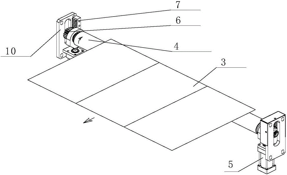
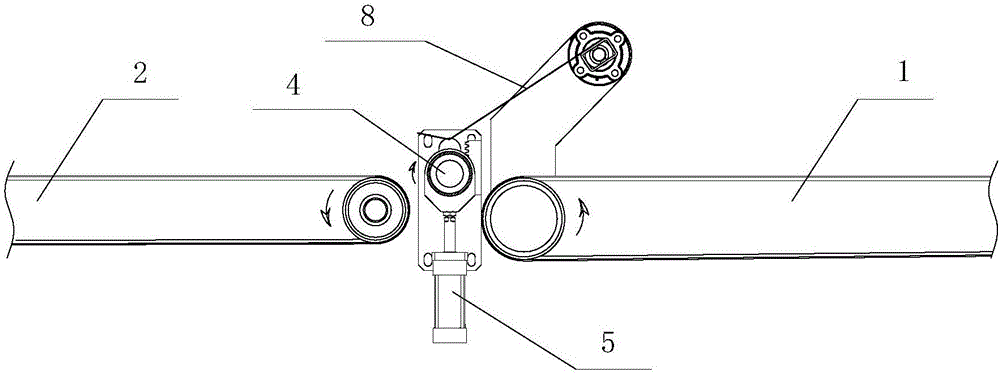
[0022] combine figure 1 , 2 Describe this embodiment, a batching device applied to the conveying mechanism of a stacker, the conveying mechanism includes a first conveying section 1 and a second conveying section 2, paper 3 is conveyed from the first conveying section 1 to the second conveying section 2, The batching device includes a rotary jack 4 installed between the first conveying section 1 and the second conveying section 2, a cylinder 5 for driving the rotary jack 4 to move up and down, arm plates 10 located at both ends of the rotary jack 4, and The gear 6 at the two ends of the rotary push rod 4 and the rack 7 arranged vertically on the arm plate 10, the gear 6 meshes with the rack 7, and the rack 7 is arranged on the side close to the first conveying section 1. The cross section of the rotating mandrel 4 is circular, and the surface of the rotating mandrel 4 is provided with a friction layer, which is made of a layer of material with strong friction. A vertical ch...

Embodiment 2

[0026] combine image 3 Describe this embodiment, the difference between this embodiment and Embodiment 1 is that the batching device also includes a press brush 8, and the press brush 8 is arranged on the top of the first conveying section 1 near the side of the rotary ejector pin 4, and cooperates with the press brush 8 , the pulling force of the rotating mandrel 4 will be greatly strengthened, which is more conducive to batching.


PUM


Abstract

The invention discloses a batching device and method applied to a conveying mechanism of a stacking machine. The conveying mechanism comprises a first conveying section and a second conveying section, wherein an object is conveyed from the first conveying section to the second conveying section. The batching device comprises a rotating propping rod which is mounted between the first conveying section and the second conveying section, a lifting driving mechanism for driving the rotating propping rod to act up and down, arm boards which are positioned at two ends of the rotating propping rod, gears which are arranged at two ends of the rotating propping rod, and vertically-arranged racks which are arranged on the arm boards and engaged with the gears, wherein the racks are arranged at the side close to the first conveying section. According to the batching device, a transverse propping rod in the prior art is designed into the rotating propping rod; a pull force is generated by the rotating propping rod during the moving-up process, so that the slipping phenomenon can be reduced; when batching paper, the problems of inaccurate batching and unsmooth batching in long and heavy paper board batching can be solved.

Description

technical field [0001] The invention relates to the field of stackers, in particular to a batching device and a batching method applied to the conveying mechanism of the stacker. Background technique [0002] Most of the top paper batching mechanism of the stacker conveying mechanism of the corrugated cardboard production line on the market now uses a cylinder to push a horizontal ejector rod whose surface is covered with a layer of high friction material, such as Figure 4 shown. When the stacker is running, the electromagnetic valve of the cylinder of the top paper batching mechanism will act to supply compressed gas to the cylinder push-out end after receiving the batch signal. The cardboard is separated from the conveyor belt of the second conveying section, so that the cardboard stops running with the conveyor belt of the second conveying section; at the same time, the conveyor belt of the second conveying section drives the cardboard on it to continue running, so that ...

Claims


Application Information

Patent Timeline
Patent Type & Authority Applications(China)
IPC IPC(8): B65H33/10
CPCB65H33/10
Inventor 王苏革宋佳琳
Owner 青岛佳友精密机械有限公司
Learn More