
Moving device for laser repairing equipment

A laser repair and moving device technology, applied in the laser field, can solve the problems of one-way movement and low movement precision, and achieve the effect of not easy to shift and shake, and precise movement precision

Pending Publication Date: 2021-09-07
苏州科韵激光科技有限公司
View PDF0 Cites 0 Cited by
  • Summary
  • Abstract
  • Description
  • Claims
  • Application Information

AI Technical Summary

Problems solved by technology

[0003] The liquid crystal panel needs to be placed on the mobile device of the laser repair equipment for positioning when the liquid crystal panel is repaired by laser. Repair the defect point, but the moving device on the current laser repair equipment can only move in one direction, and the movement accuracy is low, it is difficult to accurately move and locate the defect point on the liquid crystal panel to the laser head

Method used


Image

  • Moving device for laser repairing equipment
  • Moving device for laser repairing equipment
  • Moving device for laser repairing equipment

Examples


Embodiment 1

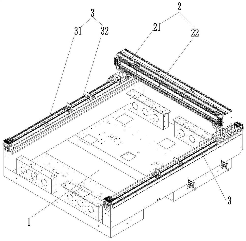
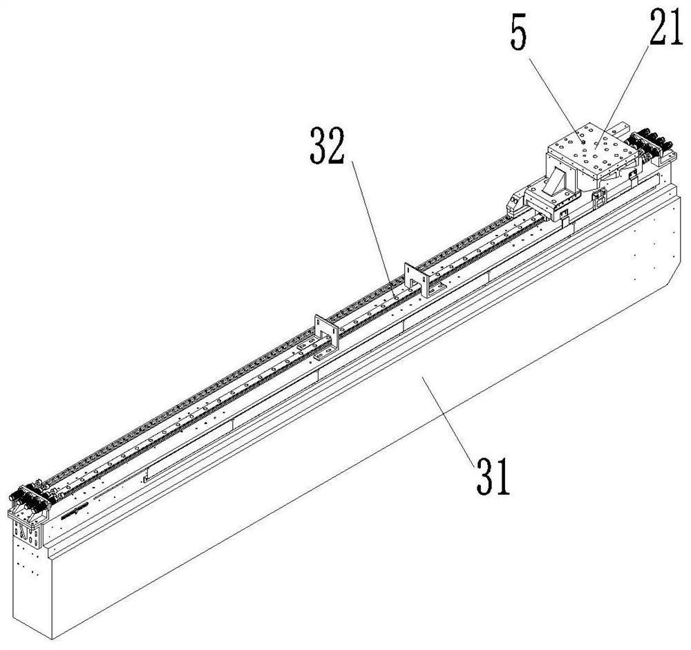
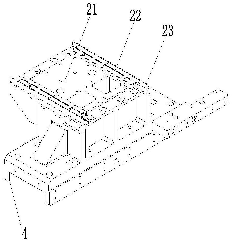
[0023] Embodiment 1: This embodiment provides a mobile device for laser repair equipment, refer to Figure 1 to Figure 3 As shown, it includes a mounting table 1 installed on the table of the laser repair equipment, an X-axis moving mechanism 2 and a Y-axis moving mechanism 3. The X-axis moving mechanism 2 is movably installed on the Y-axis moving mechanism 3 and moves along the Y-axis moving mechanism 3. X Axis moving mechanism 2 is perpendicular to Y-axis moving mechanism 3; mounting table 1, X-axis moving mechanism 2 and Y-axis moving mechanism 3 are all arranged horizontally, X-axis moving mechanism 2 is connected with the component to be repaired (not shown), and Y-axis moves There are at least two mechanisms 3 and they are equidistantly arranged along the length direction of the X-axis moving mechanism 2 .

[0024] Exemplary, see figure 1 As shown, in this embodiment, the mounting table 1, the X-axis moving mechanism 2 and the Y-axis moving mechanism 3 are all arranged ...


PUM


Abstract

The invention discloses a moving device for laser repairing equipment, which comprises a mounting table, an X-axis moving mechanism and a Y-axis moving mechanism, the mounting table is mounted on the table top of the laser repairing equipment, the X-axis moving mechanism is movably mounted on the Y-axis moving mechanism and moves along the Y-axis moving mechanism, and the X-axis moving mechanism is perpendicular to the Y-axis moving mechanism; the mounting table, the X-axis moving mechanisms and the Y-axis moving mechanisms are all horizontally arranged, the X-axis moving mechanisms are connected with a to-be-repaired assembly, and the at least two Y-axis moving mechanisms are arranged in the length direction of the X-axis moving mechanisms at equal intervals; and the X-axis moving mechanism is movably installed on the Y-axis moving mechanism and moves along the Y-axis moving mechanism, and the to-be-repaired assembly is connected to the X-axis moving mechanism so as to be capable of moving and positioning in the X direction and the Y direction. And at least two Y-axis moving mechanisms are arranged in the length direction of the X-axis moving mechanism at equal intervals, so that the X-axis moving mechanism is supported more stably, the X-axis moving mechanism is not prone to shifting and shaking, and the moving precision is higher.

Description

technical field [0001] The invention relates to the field of laser technology, in particular to a moving device for laser repair equipment. Background technique [0002] Liquid crystal panels are widely used in electronic equipment components. Before being installed in electronic equipment, LCD panels need to undergo display inspection to detect whether the LCD panel is defective. The LCD panel without defects can be directly applied to electronic equipment. If a defective liquid crystal panel is detected, it needs to be repaired by laser repair equipment. [0003] The liquid crystal panel needs to be placed on the mobile device of the laser repair equipment for positioning when the liquid crystal panel is repaired by laser. Repair the defect point, but the moving device on the current laser repair equipment can only move in one direction, and the movement accuracy is low, it is difficult to accurately move and locate the defect point on the liquid crystal panel to the lase...

Claims


Application Information

Patent Timeline
Patent Type & Authority Applications(China)
IPC IPC(8): G02F1/13
CPCG02F1/1309
Inventor 鲍国庆黄阳金丽花
Owner 苏州科韵激光科技有限公司
Learn More