
Fuel filler assembly and manufacturing method thereof

A technology of assembly and fuel filler, which is applied in the direction of power plant, transportation and packaging, vehicle parts, etc., can solve problems such as fire hazards, and achieve the effect of preventing fire and reducing impact

Active Publication Date: 2019-06-28
KOREA FUEL TECH
View PDF7 Cites 0 Cited by
  • Summary
  • Abstract
  • Description
  • Claims
  • Application Information

AI Technical Summary

Problems solved by technology

Therefore, there is a problem that there is a fire hazard due to oil leakage

Method used


Image

  • Fuel filler assembly and manufacturing method thereof
  • Fuel filler assembly and manufacturing method thereof
  • Fuel filler assembly and manufacturing method thereof

Examples


Embodiment Construction

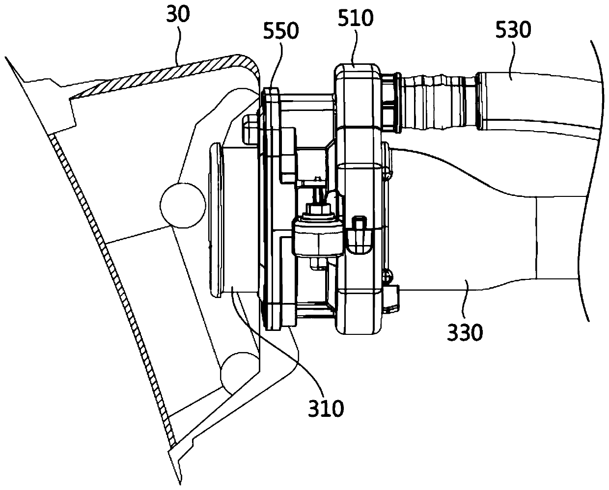
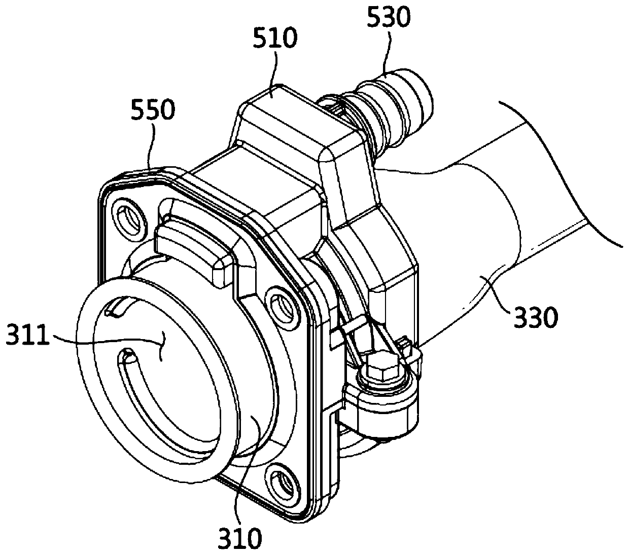
[0036] Embodiments of the present invention will be described in detail with reference to the following drawings. However, this embodiment is not limited to the embodiments disclosed below, but can be realized in various ways. Only this embodiment is intended to make the disclosure of the present invention complete and fully inform the scope of the invention to those skilled in the art to which the present invention pertains. The shapes of elements in the drawings may be exaggerated for clearer description, and the same reference numerals denote the same elements in the drawings.

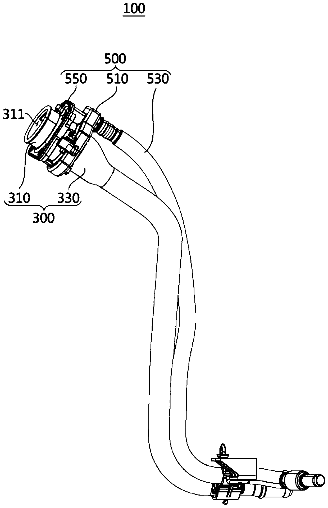
[0037] figure 1 It is a perspective view showing the fuel filler assembly according to this embodiment.

[0038] Such as figure 1 As shown, a fuel gun (not shown) is inserted into the fuel filler assembly 100 according to this embodiment. Wherein, the fuel filler assembly 100 may include: a fuel supply part 300 for transferring fuel from a fuel filler gun to the fuel tank; an air supply part 5...


PUM


Abstract

The present invention provides a filler neck assembly capable of minimizing gas leakage to the outside and a method for manufacturing the filler neck assembly. The filler neck assembly is connected to an external refueling nozzle and guides supply of fuel from the refueling nozzle to a fuel tank and comprises: a cap holder into which the refueling nozzle is inserted; and a filler pipe having a nozzle support region mutually coupled to the cap holder and supporting the refueling nozzle, and a pipe region integrally extended from the nozzle support region and interconnecting the nozzle support region and the fuel tank.

Description

technical field [0001] The invention relates to a fuel filler assembly and a manufacturing method thereof. In more detail, it is related with the fuel filler assembly which guides the fuel which flowed in from the fuel nozzle to a fuel tank, and its manufacturing method. Background technique [0002] Generally, a car can be powered by a variety of fuels such as gasoline, light oil, liquefied petroleum gas (LPG: Liquefied Petroleum Gas), liquefied natural gas (LNG: Liquefied Natural Gas), compressed natural gas (CNG: Compressed Natural Gas), etc. . The multiple fuels of this car are stored inside the fuel tank through the filling port. [0003] On the one hand, if Figure 7 As shown, the existing fuel filler assembly 10 may include a cap holder 11 , a fuel filler conduit 13 and a fuel filler tube 15 . Among them, the cap holder 11 forms a region for inserting a fuel gun (not shown). Moreover, the oil filling conduit 13 is interposed between the cap holder 11 and the oil i...

Claims


Application Information

Patent Timeline
Patent Type & Authority Patents(China)
IPC IPC(8): B60K15/04
CPCB60K15/04B60K2015/047B60K2015/0474B60K2015/049
Inventor 裵基卿金基弘蔡明根
Owner KOREA FUEL TECH
Learn More