
Novel intravenous drip hanger

A new technology, applied in the field of medical machinery, can solve the problems of obtaining and lacking through pharmacology, immunology or metabolism, and achieve the effect of simple disassembly, convenient storage and convenient movement.

Inactive Publication Date: 2017-03-15
安庆市柯旷动物药业有限公司
View PDF3 Cites 2 Cited by
  • Summary
  • Abstract
  • Description
  • Claims
  • Application Information

AI Technical Summary

Problems solved by technology

[0002] Medical devices refer to instruments, equipment, utensils, in vitro diagnostic reagents and calibrators, materials, and other similar or related items that are directly or indirectly used on the human body, including the required computer software. The utility is mainly obtained through physical means, not through Obtained by means of pharmacology, immunology or metabolism, or although these methods are involved but only play an auxiliary role, the purpose is diagnosis, prevention, monitoring, treatment or alleviation of disease; diagnosis, monitoring, treatment, alleviation or functional compensation of injury; Inspection, replacement, adjustment or support of physiological structures or physiological processes; life support or maintenance; pregnancy control; providing information for medical or diagnostic purposes by examining samples from the human body. A drip hanger that is convenient to move and lift. During the use of the drip hanger, patients often need to move. The existing drip hanger lacks this convenient device

Method used


Image

  • Novel intravenous drip hanger
  • Novel intravenous drip hanger
  • Novel intravenous drip hanger

Examples


Embodiment Construction

[0015] The embodiments of the present invention will be described in detail below with reference to the accompanying drawings, but the present invention can be implemented in many different ways defined and covered by the claims.

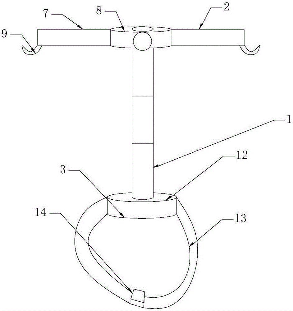
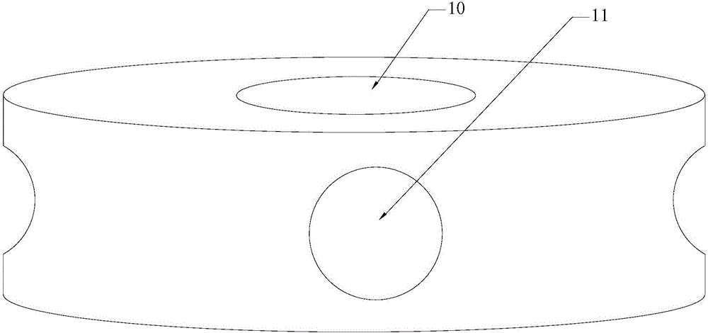
[0016] As shown in the accompanying drawings, a new drip hanger includes a support rod 1, a hanger 2 installed on one end of the support rod 1 and a fixing device 3 installed on the other end of the support rod 1. The support rod 1 is composed of several support shafts 4 One end of the supporting shaft 4 is provided with a mounting shaft 5, the side of the mounting shaft 5 is provided with threads, the other end of the supporting shaft 4 is provided with a mounting hole 6, and the mounting hole 6 is provided with threads, the mounting hole 6 is matched with the mounting shaft 5, and the supporting shaft 4 The other end side is provided with threads, the support shaft 4 is a stainless steel hollow cylinder with a bottom diameter of 3 cm and a height o...


PUM


Abstract

The invention discloses a novel intravenous drip hanger. The novel intravenous drip hanger comprises a supporting rod, a hanging rod arranged at one end of the supporting rod and a fixing device arranged at the other end of the supporting rod, wherein the supporting rod comprises a plurality of supporting shafts; an installing shaft is arranged at one end of each supporting shaft; a thread is arranged on the side surface of each installing shaft; an installing hole is formed in the other end of each supporting shaft, and a thread is arranged in the installing hole; the installing hole is matched with the installing shaft; a thread is arranged on the side surface of the other end of each supporting shaft; the hanging rod comprises a connecting rod, a base and a pothook; the pothook is welded at one end of the connecting rod; a thread is arranged on the side surface of the other end of the connecting rod; fixing holes are formed in the end surface of the base, threads are arranged in the fixing holes, and the fixing holes are matched with the supporting shafts; the fixing device comprises a fixed tray, a binding rope arranged on the side surface of the fixed tray and a locking device arranged on the binding rope; and holes are formed in the end surface of the fixed tray, threads are arranged in the holes, and the holes are matched with the installing shafts. The novel intravenous drip hanger is convenient to move and store and simple to disassemble, and is fixed on a human body and moves along with the human body.

Description

technical field [0001] The invention belongs to the technical field of medical machinery, in particular to a novel drip hanger. Background technique [0002] Medical devices refer to instruments, equipment, utensils, in vitro diagnostic reagents and calibrators, materials, and other similar or related items that are directly or indirectly used on the human body, including the required computer software. The utility is mainly obtained through physical means, not through Obtained by means of pharmacology, immunology or metabolism, or although these methods are involved but only play an auxiliary role, the purpose is diagnosis, prevention, monitoring, treatment or alleviation of disease; diagnosis, monitoring, treatment, alleviation or functional compensation of injury; Inspection, replacement, adjustment or support of physiological structures or physiological processes; life support or maintenance; pregnancy control; providing information for medical or diagnostic purposes by ...

Claims


Application Information

Patent Timeline
Patent Type & Authority Applications(China)
IPC IPC(8): A61M5/14
CPCA61M5/1415A61M5/1417A61M2005/1416
Inventor 刘嘉魁彭军红
Owner 安庆市柯旷动物药业有限公司
Learn More