Device and method of mega-kilowatt class nuclear power plant delay relay fault diagnosis
A technology of fault diagnosis device and time delay relay, which is applied in measuring devices, circuit breaker testing, instruments, etc., can solve the problems of equipment site safety and stability risks, delay relay failures, equipment shutdown actions, etc. operating environment, improved reliability, and improved cognitive effects
- Summary
- Abstract
- Description
- Claims
- Application Information
AI Technical Summary
Problems solved by technology
Method used
Image
Examples
Embodiment 1
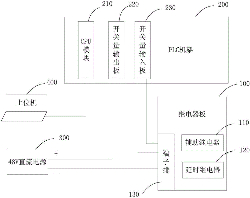
[0033] See figure 1 The delay relay fault diagnosis device for a mega-kilowatt nuclear power plant proposed in the first embodiment has a relay board 100, a PLC rack 200, and a DC power supply 300. The DC power supply 300 uses a 48V DC power supply as an example.
[0034] The relay board 100 has an auxiliary relay assembly base and a delay relay assembly base, the auxiliary relay assembly base is equipped with an auxiliary relay 110, and the delay relay assembly base is equipped with a delay relay 120 that requires fault diagnosis.
[0035] The PLC rack 200 has a CPU module 210, a switch output board 220, and a switch input board 230. The DC power supply 300 and the CPU module 210 are respectively connected to the switch output board 220 with electrical signals to control the switch output board 220 to use the DC power supply 300 to generate a driving signal, which is generally a square wave signal. The switch output board 220 is also connected to the electrical signal of the delay...
Embodiment 2
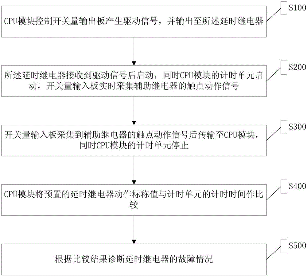
[0039] please at figure 1 On the basis of figure 2 , The method for diagnosing the delay relay fault of a million-kilowatt nuclear power plant in the second embodiment adopts the fault diagnosis device for the delay relay of a million-kilowatt nuclear power plant in the first embodiment, and includes the following steps S100 to S500:
[0040] S100. The CPU module controls the switch output board to generate a driving signal and output to the delay relay.
[0041] S200. The delay relay is started after receiving the drive signal, and at the same time the timing unit of the CPU module is started, and the switch input board collects the contact action signal of the auxiliary relay in real time.
[0042] S300. The switch input board collects the contact action signal of the auxiliary relay and transmits it to the CPU module, and at the same time the timing unit of the CPU module stops.
[0043] S400, the CPU module compares the preset nominal value of the delay relay action with the timin...
Embodiment 3
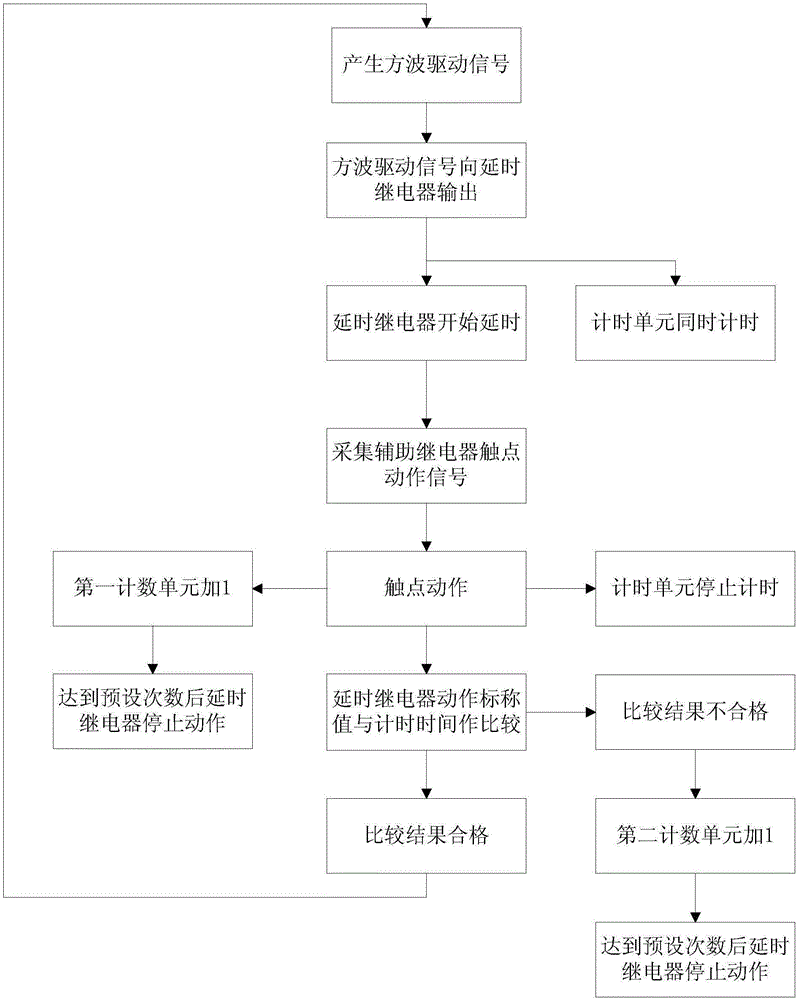
[0047] please at figure 2 On the basis of image 3 The method for diagnosing the delay relay fault of a million-kilowatt nuclear power plant proposed in the third embodiment is further refined and optimized on the basis of the second embodiment. Specifically, step S300 also includes: the first counting unit of the CPU module automatically adds 1 After step S300, it also includes: S310, when the first counting unit of the CPU module has not reached the preset number of times, repeat steps S100 to S300.
[0048] In this embodiment, the setting of the first counting unit facilitates the recurrence of the diagnosis process and reduces misdiagnosis. In step S500, the fault condition of the delay relay can be diagnosed based on the comparison results corresponding to the preset times of the first counting unit. If the digital input board can collect the preset number of action signals from the contacts of the auxiliary relay, it means that the delay relay can operate (but the delay m...
PUM
 Abstract
Description
Claims
Application Information
 - R&D
- Intellectual Property
- Life Sciences
- Materials
- Tech Scout
- Unparalleled Data Quality
- Higher Quality Content
- 60% Fewer Hallucinations
Browse by: Latest US Patents, China's latest patents, Technical Efficacy Thesaurus, Application Domain, Technology Topic, Popular Technical Reports.
© 2025 PatSnap. All rights reserved.Legal|Privacy policy|Modern Slavery Act Transparency Statement|Sitemap|About US| Contact US: help@patsnap.com


