Automatic air energy dryer for grain drying

An air energy drying and grain drying technology, which is applied in grain drying, drying machine, drying gas arrangement, etc., can solve the problems of low efficiency and increased labor cost, and achieve good drying effect, convenient and ingenious use, and easy operation Effect

Inactive Publication Date: 2017-03-08
HUBEI KEYANG ENERGY SAVING EQUIP
View PDF8 Cites 7 Cited by
  • Summary
  • Abstract
  • Description
  • Claims
  • Application Information

AI Technical Summary

Problems solved by technology

[0002] With the rapid development of science and technology, energy conservation and environmental protection have become an important indicator of the development of science and technology. The conservation and utilization of energy can reduce environmental pollution and save costs. Nowadays, the energy on the earth is getting less and less, and the use of new energy can In line with the needs of modern technology, air energy should also be widely used. If air energy is used in the dryer, it can not only achieve a good drying effect, but also save energy and protect the environment. Nowadays, high-temperature dryers are widely used in various fields. Including agricultural products, chemical products, hardware products, etc., it has the advantages of less energy consumption, less environmental pollution, and a wide range of applications. However, the existing grain dryers have low efficiency and require manual operation, resulting in increased labor costs.

Method used


Image

  • Automatic air energy dryer for grain drying
  • Automatic air energy dryer for grain drying

Examples


Embodiment Construction

[0014] The following will clearly and completely describe the technical solutions in the embodiments of the present invention with reference to the accompanying drawings in the embodiments of the present invention. Obviously, the described embodiments are only some, not all, embodiments of the present invention.

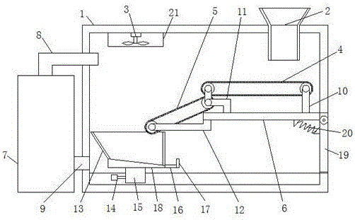
[0015] refer to Figure 1-2 , an automatic air energy dryer for grain drying, comprising a body shell 1, a feed funnel 2 is provided at the upper end of the body shell 1, and the feed funnel 2 passes through the top wall of the body shell 1 and extends toward the direction, the body shell 1 A support plate 6 is provided on one side of the inner wall, a first support 10 and a second support 11 are provided on the support plate 6, a connecting shaft is provided at one end of the second support 11, and a first transmission is provided between the first support 10 and the connecting shaft. In the device 4, the end of the connecting shaft away from the first transmission ...


PUM


Abstract

The invention discloses an automatic air energy dryer for grain drying. The dryer comprises a body housing, wherein a feed hopper is arranged at the upper end of the body housing; a support plate is arranged on one side of the inner wall of the body housing; a first transmission device is arranged between a first support column and a connecting shaft; a second transmission device is arranged at the end, far away from the first transmission device, of the connecting shaft; a collection box is arranged at one end of the second transmission device; an inclined block is arranged at the bottom of the collection box; a sliding block is fixedly connected to the lower end of the inclined block; a box door is connected to one side of the outer wall of the body housing in a rotating manner; a spring is fixedly connected between one side of the box door and the bottom of the support plate; an air outlet pipe is arranged on the other side of the outer wall of the body housing; a drying device is arranged at the end, far away from the body housing, of the air outlet pipe. The dryer is simple in structure, easy to operate, convenient and ingenious in use and suitable for wide popularization, and has good drying effects, and grains can be automatically dried.

Description

technical field [0001] The invention relates to the technical field of drying equipment, in particular to an automatic air energy dryer for grain drying. Background technique [0002] With the rapid development of science and technology, energy saving and environmental protection have become an important indicator of the development of science and technology. The conservation and utilization of energy can reduce environmental pollution and save costs. Nowadays, the energy on the earth is getting less and less, and the use of new energy can In line with the needs of modern technology, air energy should also be widely used. If air energy is used in the dryer, it can not only achieve a good drying effect, but also save energy and protect the environment. Nowadays, high-temperature dryers are widely used in various fields. Including agricultural products, chemical products, hardware products, etc., it has the advantages of less energy consumption, less environmental pollution, a...

Claims


Application Information

Patent Timeline
IPC IPC(8): F26B17/04F26B21/00F26B23/00F26B25/00A23B9/08
CPCA23B9/08F26B17/04F26B21/00F26B23/00F26B25/002F26B2200/06
Inventor 赵大富
Owner HUBEI KEYANG ENERGY SAVING EQUIP
Why Eureka
Try Eureka