
hydrostatic axial piston machine

A technology of axial piston machine and hydrostatic force, which is applied to reciprocating piston engines, liquid displacement machinery, mechanical equipment, etc., can solve the problems of reducing the efficiency of axial piston machines, achieve precise adjustment, and reduce leakage losses Effect

Active Publication Date: 2020-07-17
ROBERT BOSCH GMBH
View PDF6 Cites 0 Cited by
  • Summary
  • Abstract
  • Description
  • Claims
  • Application Information

AI Technical Summary

Problems solved by technology

[0004] A disadvantage of this solution is that the pressure medium connection of the relief pressure bag to its pressure medium source is continuous, so that the continuous leakage flow through the relief pressure region and thus the loss of pressure medium and energy reduces the axial piston machine efficiency

Method used


Image

  • hydrostatic axial piston machine
  • hydrostatic axial piston machine
  • hydrostatic axial piston machine

Examples


Embodiment Construction

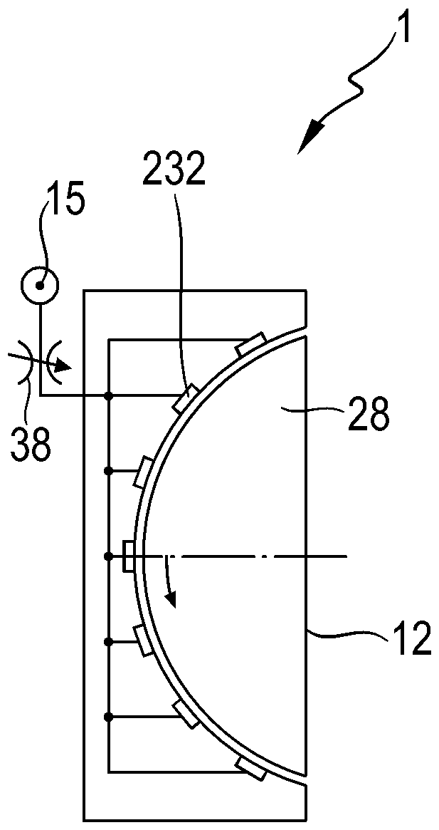
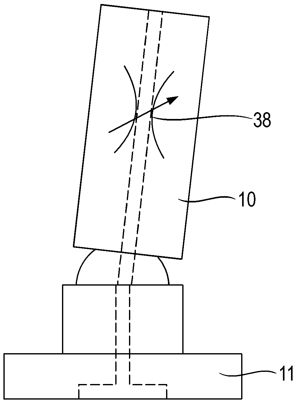
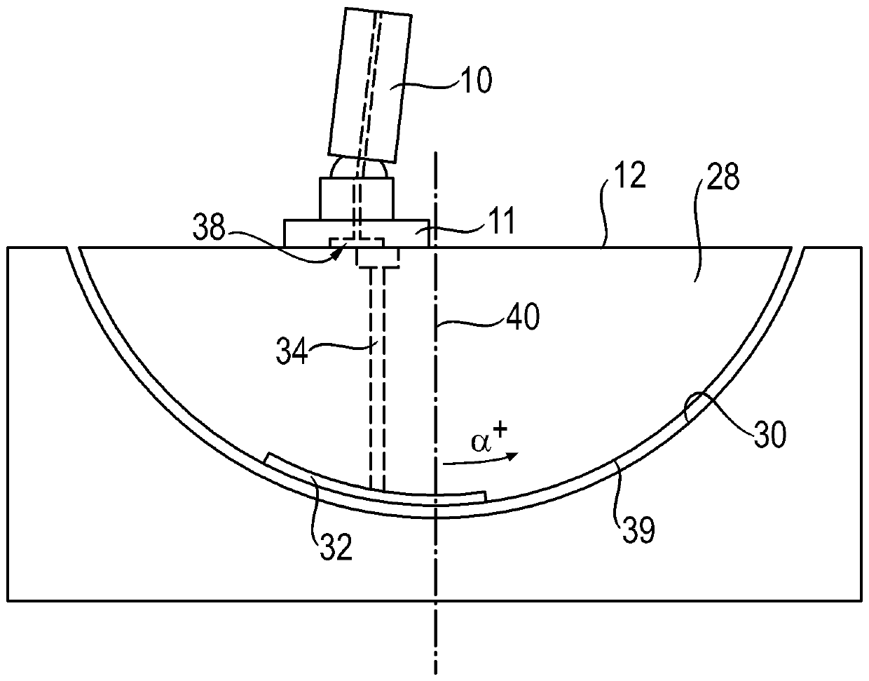
[0050] figure 1 A hydrostatic axial piston machine 1 is shown in longitudinal section. In the exemplary embodiment shown, this axial piston machine is designed as a hydraulic pump and therefore has a firmly assigned high-pressure connection HD and a firmly arranged low-pressure connection ND, which are formed on the housing cover 2 and at the figure 1 is not displayed. The drive shaft 4 is driven in rotation about the axis of rotation 3 and carries a cylinder 6 , in which a plurality of cylinder bores 8 arranged distributed over the circumference are provided, in which corresponding working cylinders are guided along the axial direction. Piston 10. The working pistons 10 are supported slidingly on sliding surfaces 12 of the pivoting cradle 13 via sliding shoes 11 . The last-mentioned cradle does not rotate, but can be adjusted in its inclination via the adjusting cylinder 14 of the adjusting device. In this way, the swivel angle α and thus the displacement volume of the ax...


PUM


Abstract

A hydrostatic axial piston machine defines an adjustable displacement volume and includes a housing, a cylinder drum, a plurality of working pistons, a pivot cradle, and a plain bearing. The working pistons are received in the cylinder drum so as to be axially displaceable, and are supported on a sliding surface of the pivot cradle. The pivot cradle is configured to adjust the displacement volume, and is pivotably mounted on the plain bearing. The plain bearing is fixed with respect to the housing. The hydrostatic axial piston machine is configured to form at least one first hydrostatic relief pressure field between the plain bearing and the pivot cradle.

Description

technical field [0001] The invention relates to a hydrostatic axial piston machine according to the invention. Background technique [0002] An axial piston machine of this type is shown, for example, in DE 10 2012 022 999 A1. The axial piston machine has an adjustable displacement volume in a swash plate design and has a cylinder connected to the drive shaft in a rotationally fixed manner, in which cylinders are formed approximately parallel to the axis of rotation of the drive shaft hole. In each case a working piston is accommodated axially movable in the cylinder bores. In this case, the working piston is supported on a slide surface of a pivot cradle which is pivotably mounted on slide bearings fastened to the housing for adjustment of the displacement volume. [0003] In order to improve the sliding of the cradle on the plain bearing and to reduce the load on the friction surfaces, a hydrostatic relief pressure zone is provided, which can be formed on the cradle sid...

Claims


Application Information

Patent Timeline
Patent Type & Authority Patents(China)
IPC IPC(8): F04B1/324F04B1/24F04B1/30F04B1/2035F04B1/2085F04B1/2064F04B49/06F04B49/08F04B49/22F03C1/06F03C1/253F03C1/40F03C1/32
CPCF04B1/24F04B1/324F03C1/0686F04B1/328F04B49/06F04B1/124F04B1/143F04B1/145F04B1/148F04B1/29F04B49/08F04B49/225
Inventor S.豪格F.诺特J.勒姆R.舍雷尔
Owner ROBERT BOSCH GMBH
Learn More