Wave power generation device and control method
A technology of wave power generation and control methods, applied in safety devices, hydroelectric power generation, ocean energy power generation, etc., can solve the problems of low energy conversion efficiency and high price, achieve high energy conversion efficiency, improve power generation efficiency, and have a wide range of applications Effect
- Summary
- Abstract
- Description
- Claims
- Application Information
AI Technical Summary
Problems solved by technology
Method used
Image
Examples
Embodiment 1
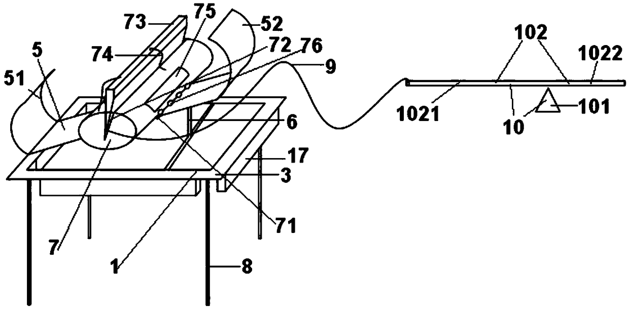
[0053] like figure 1 , figure 2 The shown embodiment is a wave power generation device, including a controller 2, a power generating mechanism, a support frame 1 located on the water, a buoy 3 located on the edge of the support frame, an inclined guide rail 5 located on the support frame, for The support column 6 supporting the inclined guide rail, the swing body 7 arranged on the inclined guide rail, the 4 cables 8 arranged on the support frame, the stay rope 9 arranged on the swing body and the lever 10 positioned above the support frame; one end of the lever is connected with The pull rope is connected, and the other end of the lever is connected to the generator through the connecting rope; each cable is provided with an anchor at the lower end;
[0054] Both sides of the oscillating body are provided with bending plates 71 that match the edges of the inclined guide rails. The oscillating body is provided with a V-shaped groove 72, and the V-shaped groove is provided wit...
Embodiment 2
[0073] Embodiment 2 includes all structures and step parts of Embodiment 1, such as Figure 4 , Figure 5 , figure 2 As shown, each cable in Embodiment 2 includes an elastic tube with a closed lower end, and a plurality of metal sleeves 81 that are sequentially inserted on the elastic tube; the upper end of the elastic tube of each cable is connected to the outlet pipe of the air pump 82 , each elastic tube is provided with an air pressure sensor 86, and each air pressure sensor and air pump are electrically connected to the controller.
[0074] The metal sleeve includes a tapered insertion section 83 located at the lower part of the metal sleeve, an upwardly flared horn section 84 positioned at the upper part of the metal sleeve for matching with the insertion section of the adjacent metal sleeve, and a horn section 84 located between the insertion section and the horn. Connect segment 85 between segments.
[0075] The step 100 of embodiment 1 also includes a control step...
Embodiment 3
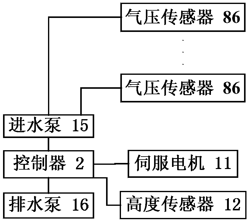
[0081] Embodiment 3 includes all structures and steps of Embodiment 1, and the support frame of Embodiment 3 is also provided with such figure 1 , figure 2 The water inlet pump 15, the drainage pump 16 and the four ballast tanks 17 are shown, the water inlet pump and the drainage pump are connected to each ballast tank through water pipes, and the water inlet pump and the drainage pump are electrically connected to the controller;
[0082] (8-1) When B≥2.5W, the controller controls the servo motor to drive the screw to rotate, so that the upper end of the support column is lowered to the water surface;
[0083] And the controller controls the water inlet pump to pump water into each ballast tank. After the water inlet pump pumping time reaches T1=3 minutes, the controller controls the water inlet pump to stop working;
[0084] (8-2) When B<2.5W, the controller controls the drainage pump to pump water out of each ballast tank. After the drainage time of the drainage pump reac...
PUM
 Abstract
Description
Claims
Application Information
 - R&D Engineer
- R&D Manager
- IP Professional
- Industry Leading Data Capabilities
- Powerful AI technology
- Patent DNA Extraction
Browse by: Latest US Patents, China's latest patents, Technical Efficacy Thesaurus, Application Domain, Technology Topic, Popular Technical Reports.
© 2024 PatSnap. All rights reserved.Legal|Privacy policy|Modern Slavery Act Transparency Statement|Sitemap|About US| Contact US: help@patsnap.com


