
Double-frequency induction quenching load device

A load device and dual-frequency induction technology, which is applied in the direction of quenching device, furnace type, furnace, etc., can solve the problems of high-frequency and medium-frequency induction heat treatment that cannot be alternated, and achieve the effects of wide application range, long service life and cost saving

Inactive Publication Date: 2017-03-08
SHIYAN HENGJIN INDUCTION TECH CO LTD
View PDF1 Cites 4 Cited by
  • Summary
  • Abstract
  • Description
  • Claims
  • Application Information

AI Technical Summary

Problems solved by technology

[0003] The invention provides a dual-frequency induction hardening load device, the purpose of which is to solve the problem that high-frequency and medium-frequency induction heat treatment cannot be alternated

Method used


Image

  • Double-frequency induction quenching load device
  • Double-frequency induction quenching load device

Examples


Embodiment Construction

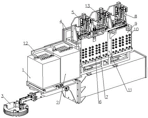
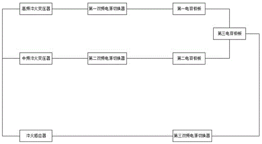
[0008] Such as figure 1 As shown, a dual-frequency induction quenching load device includes a high-frequency quenching transformer 1, a medium-frequency quenching transformer 2, and a quenching inductor 3. The input end of the high-frequency quenching transformer 1 is switched with the first dual-frequency power supply in turn through four rows of load connections. The device 5 and the first capacitor plate 6 are connected in series, and the first capacitor plate 6 is provided with a fixedly connected high-frequency capacitor 7; the input end of the intermediate frequency quenching transformer 2 is sequentially connected to the second dual-frequency power switch 8 through the load connection row 4 and the second capacitor plate 9 in series, the second capacitor plate 9 is provided with a fixedly connected intermediate frequency capacitor 10; the input ends of the first capacitor plate 6 and the second capacitor plate 9 are connected with the third capacitor plate 11, That is, ...


PUM


Abstract

A double-frequency induction quenching load device comprises a high-frequency quenching transformer, a medium-frequency quenching transformer and a quenching inductor. The input end of the high-frequency quenching transformer is sequentially connected with a first double-frequency power switcher and a first capacitor pole plate in series through a load connecting bar, and fixedly-connected high-frequency capacitors are arranged on the first capacitor pole plate. The input end of the medium-frequency quenching transformer is sequentially connected with a second double-frequency power switcher and a second capacitor pole plate in series through the load connecting bar, and fixedly-connected medium-frequency capacitors are arranged on the second capacitor pole plate. The input end of the first capacitor pole plate and the input end of the second capacitor pole plate are connected with a third capacitor pole plate. The output end of the high-frequency quenching transformer and the output end of the medium-frequency quenching transformer are sequentially connected with the quenching inductor, a third double-frequency power switcher and the third capacitor pole plate in series through a busbar to form a circulation circuit. The device is wide in application range, parts of quenching structures can be inducted well, the service life of a workpiece is longer, the cost is reduced, pollution to the environment is small, and the quenching efficiency is high.

Description

technical field [0001] The invention belongs to the field of quenching devices, in particular to a dual-frequency induction quenching load device. Background technique [0002] At present, for workpieces with convex and concave surface structures such as gears, conventional single-frequency induction heating technology cannot achieve satisfactory induction heat treatment effects when induction heating is used. Due to the convex and concave surfaces of the gear, high-frequency induction heating is used to quench the surface of the tooth part. The heat generated by the induced current is quickly transmitted to the center of the gear, and the top of the tooth is completely hardened, but the hardening of the tooth root is insufficient. In addition, this treatment method is also easy to increase residual stress on the heel tooth surface, resulting in fracture. Medium frequency induction heating is also used to quench the surface of the tooth part of the gear. The heat is conduct...

Claims


Application Information

Patent Timeline
Patent Type & Authority Applications(China)
IPC IPC(8): C21D1/10C21D1/62C21D9/32
CPCY02P10/25
Inventor 周祥成
Owner SHIYAN HENGJIN INDUCTION TECH CO LTD
Learn More