
Light emitter

A technology of light-emitting elements and light-emitting parts, applied in optical elements, organic light-emitting devices, electrical components, etc., can solve the problem of difficulty in fully ensuring the light-emitting area of ​​the hemispherical lens surface, and achieve high contrast, excellent weather resistance and corrosion resistance. Effect

Inactive Publication Date: 2017-02-22
JX NIPPON OIL & ENERGY CORP
View PDF16 Cites 1 Cited by
  • Summary
  • Abstract
  • Description
  • Claims
  • Application Information

AI Technical Summary

Problems solved by technology

[0005] Since the light-emitting layer in the organic layer of the organic EL element described in this document is patterned and has a quadrangular shape, it is difficult to sufficiently ensure the light-emitting area of ​​the hemispherical lens surface provided on the back surface of the substrate, and further improvement in light-emitting efficiency is desired. improve

Method used


Image

  • Light emitter
  • Light emitter
  • Light emitter

Examples


Embodiment 1

[0206] Toluene was added and dissolved in 230 mg of BCP manufactured by Polymer Source and 57.5 mg of polyethylene glycol 2050 manufactured by Aldrich as polyethylene oxide (number average molecular weight (Mn) = 2050) to make the total amount 15 g. , and then filtered through a membrane filter with a pore size of 0.5 μm to obtain a BCP solution.

[0207] The BCP used will be described below.

[0208] BCP is composed of PS-PMMA segments, the Mn of PS segment is 680000, the Mn of PMMA segment is 580000, the Mn of BCP is 1260000, the volume ratio of PS segment to PMMA segment is 57:43, and the molecular weight distribution The (Mw / Mn) was 1.28, the glass transition temperature (Tg) of the PS segment was 107°C, and the Tg of the PMMA segment was 134°C.

[0209] The volume ratio of the PS segment and the PMMA segment is that the density of PS is 1.05g / cm 3 , The density of PMMA is 1.19g / cm 3computational. The Mn and Mw are measured using gel permeation chromatography columns i...

Embodiment 2

[0245] A light-emitting element was produced in the same manner as in Example 1, except that the masks used for the patterns of the transparent electrode layer and the metal electrode layer were changed, and the diameter D2 of the light-emitting portion was changed to 9.0 mm. r1 of the obtained light-emitting device was 0.90, and r2 was 0.07. In addition, the light emitting area was measured in the same manner as in Example 1. The results are shown in Table 1 and Figure 6 (6b).


PUM

PropertyMeasurementUnit
Average spacingaaaaaaaaaa
Diameteraaaaaaaaaa
Diameteraaaaaaaaaa

Abstract

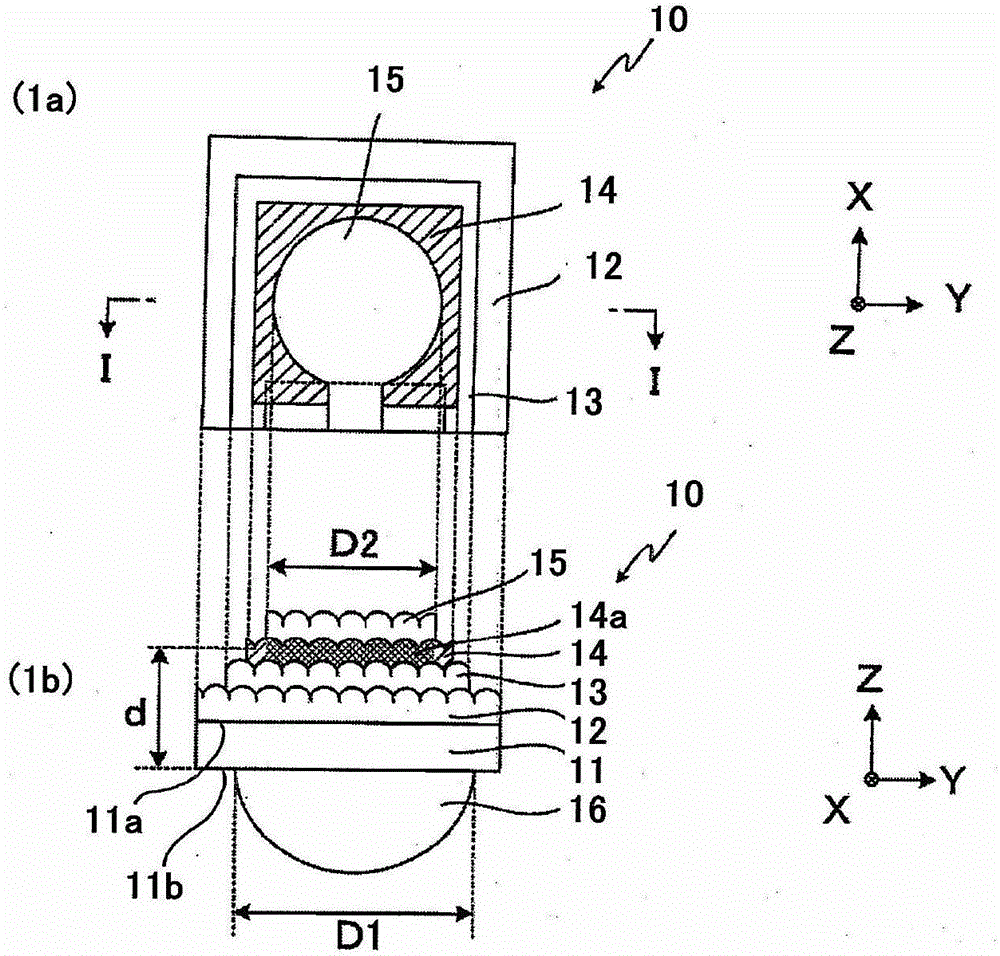
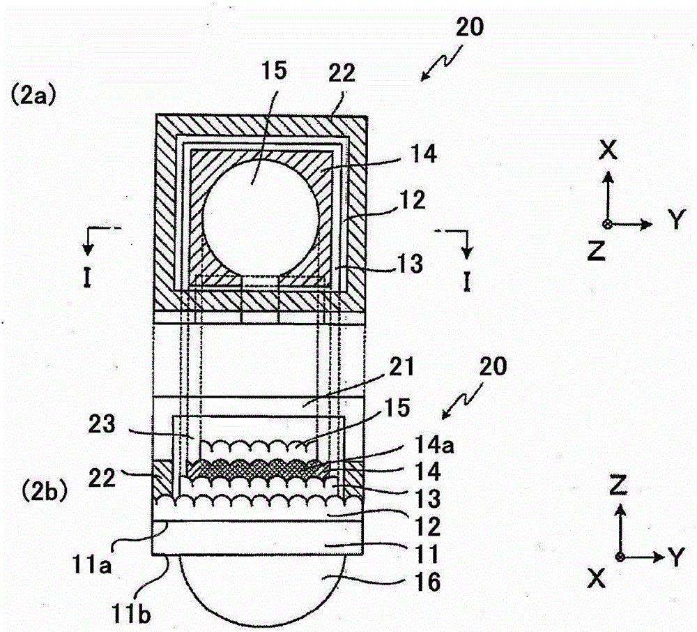
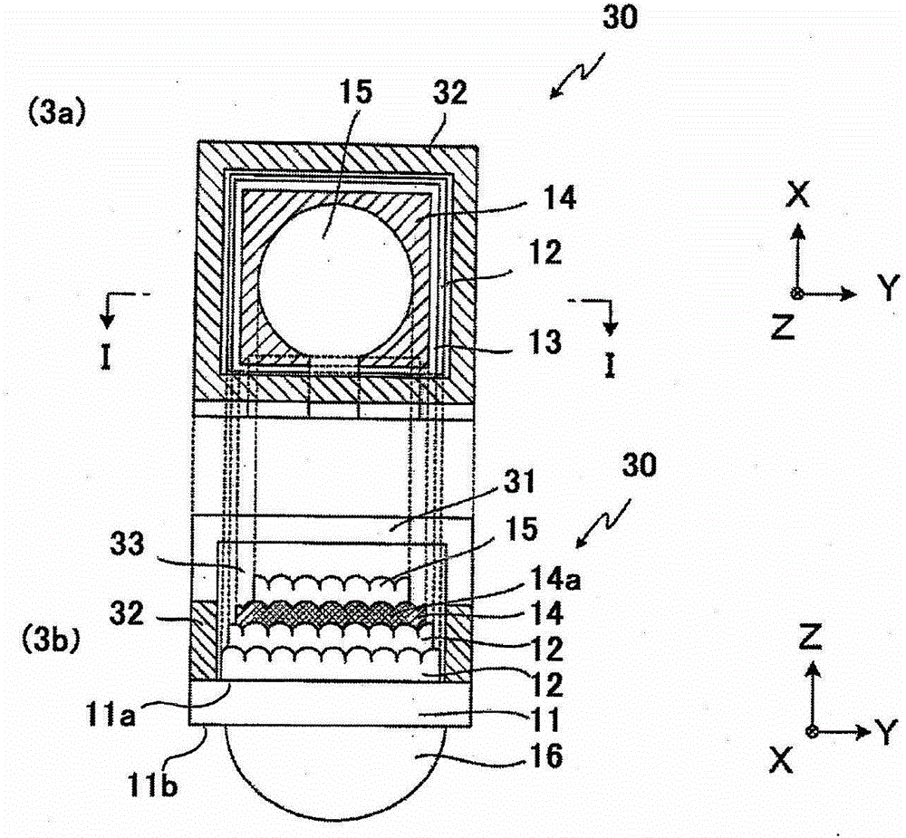
Provided is a light emitter with which it is possible to take emitted light to the outside with high efficiency and to ensure a sufficient light-emitting area. A light emitter (10) is characterized by including a translucent substrate (11) that has a first and a second surface, an uneven structural layer (12) that has an uneven pattern, a first electrode layer (13), an organic light-emitting layer (14) that has a light-emitting part, a second electrode layer (15), and a lens member (16) that has a diameter of D1; the uneven structural layer, the first electrode layer, the organic light-emitting layer, and the second electrode layer forming a layered body in the stated order from the first surface of the substrate; the uneven pattern being close to the first electrode layer of the uneven structural layer; the substrate having the lens member on the second surface; the light-emitting part comprising a layer-shaped region of diameter D2 in the organic light-emitting layer sandwiched between the first and the second electrode layer; the light-emitting part being concentric with the lens member; and the ratio between the diameter D2 of the light-emitting part and the diameter D1 of the lens member being 0.7<D2 / D1<=1.0.

Description

technical field [0001] The present invention relates to a light-emitting element used in displays, lighting devices, automobile tail lights, and the like. Background technique [0002] Organic light-emitting diodes (OLEDs) using organic electroluminescent elements (EL) are known as light-emitting elements suitable for high-contrast, thinner, and lightweight next-generation displays and lighting devices. OLED is composed of an anode, an organic light-emitting layer and a cathode in sequence on a transparent substrate. By applying a voltage on the electrodes, holes and electrons are respectively supplied from the anode and the cathode to the organic light-emitting layer, and organic molecules are excited by the recombination of holes and electrons. To glow. In order to use the emitted light in a display device or a lighting device, it is necessary to develop a technology for efficiently extracting the light from the organic light-emitting layer onto the surface of the element...

Claims


Application Information

Patent Timeline
IPC IPC(8): H05B33/02G02B3/00G02B5/18H01L51/50H05B33/22
CPCY02E10/549H10K50/813H10K50/822H10K50/841H10K50/858H10K2101/00H10K2102/351G02B3/00G02B5/18H05B33/02H05B33/22H10K50/00H10K50/11H10K77/10
Inventor 西村凉柴沼俊彦鸟山重隆
Owner JX NIPPON OIL & ENERGY CORP
Learn More