Heat dissipation structure of electronic equipment

A technology of heat dissipation structure and electronic equipment, which is applied in the direction of modification through conduction heat transfer, cooling/ventilation/heating transformation, etc., which can solve the problems of poor heat dissipation effect and complex heat dissipation structure, and achieve simplified structure, good heat dissipation effect, and avoid heat generation serious effect

Inactive Publication Date: 2017-02-22
GREE ELECTRIC APPLIANCES INC
View PDF5 Cites 14 Cited by
  • Summary
  • Abstract
  • Description
  • Claims
  • Application Information

AI Technical Summary

Problems solved by technology

[0006] Therefore, the technical problem to be solved by the present invention is to overcome the defects of complex he...

Method used


Image

  • Heat dissipation structure of electronic equipment

Examples


Embodiment Construction

[0026] The technical solutions of the present invention will be clearly and completely described below in conjunction with the accompanying drawings.

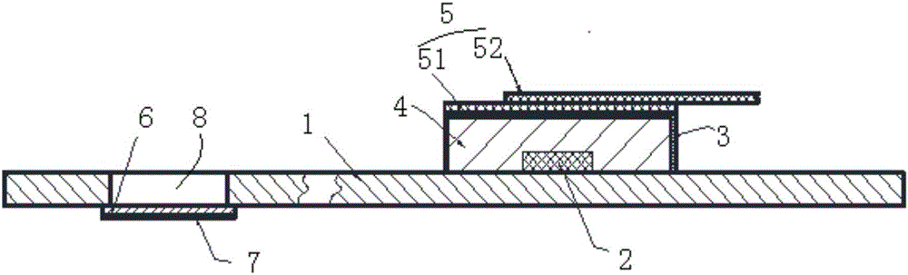
[0027] Such as figure 1 As shown, the electronic equipment in this embodiment is a mobile phone component, including an insulating base plate 1 (PCB board in this embodiment), heating components 2 (CPU in this embodiment) and a heat dissipation structure. The heat dissipation structure includes a shield cover 3 , a heat conduction component 4 , a heat dissipation component 5 , a baffle plate 6 and a heat insulation component 7 . Wherein, the shielding cover 3 independently covers the heating components 2 arranged on the insulating base plate 1; Between the inner top wall of the shield 3, fill the gap between the heating element 2 and the shield 3; the heat dissipation component 5 includes a first heat dissipation element that covers the upper surface of the shield 3 51, and a second heat sink 52 that covers part of the upper ...


PUM


Abstract

The invention provides a heat dissipation structure of electronic equipment. The heat dissipation structure comprises a shielding cover and also comprises a heat conduction part, wherein the shielding cover independently covers a heat generation component arranged on an insulation bottom plate, and the heat conduction part is connected between the heat generation component and the shielding cover. In the heat dissipation structure, the heat conduction part is used for transferring heat generated by the heat generation component during working to the shielding cover, the heat can be rapidly transferred to the shielding cover due to very short conduction path, thus, heat generated in the heat dissipation structure of the electronic equipment can be rapidly dissipated out, the heat dissipation structure of the electronic equipment has a favorable heat dissipation effect, and the problem of serous heat generation of a local part of the heat dissipation structure of the electronic equipment is avoided; and meanwhile, a steel sheet support is not needed to additionally arrange under the insulation bottom plate to conduct heat, and thus, the heat dissipation structure of the electronic equipment can be simplified.

Description

technical field [0001] The invention relates to the technical field of electronic equipment, in particular to a heat dissipation structure for electronic equipment. Background technique [0002] As the heat dissipation structure of smart phones, tablets and other electronic equipment is getting stronger and smaller, the performance requirements of the electronic components (such as CPU, memory, etc.) are also getting higher and higher. Moreover, electronic components will generate a lot of heat when they are working (especially at full load). If the heat is not dissipated in time, it will have a great impact on the stability and life of electronic components. [0003] At present, the heat dissipation structure of electronic equipment usually uses a PCB board (i.e. a printed circuit board) as the chassis of the electronic components. The PCB board is provided with several electronic components that are electrically connected to each other. The metal shielding cover for signa...

Claims


Application Information

Patent Timeline
IPC IPC(8): H05K7/20
CPCH05K7/2039
Inventor 金本凯隆冰峰毛承建李辉石明
Owner GREE ELECTRIC APPLIANCES INC
Why Eureka
Try Eureka