
Clamping device for circuit board processing

A clamping device and circuit board technology, applied in printed circuits, printed circuit manufacturing, PCB positioning during processing, etc., can solve problems such as damage to electronic components of the circuit board, inability to operate the circuit board, and inconvenient operation, to ensure stability. performance, improved accuracy, and simple structure

Inactive Publication Date: 2017-02-22
南京万云信息技术有限公司
View PDF0 Cites 4 Cited by
  • Summary
  • Abstract
  • Description
  • Claims
  • Application Information

AI Technical Summary

Problems solved by technology

[0003] At present, the clamping mechanism used to clamp the circuit board for processing and maintenance in the prior art is not reasonable enough, the circuit board cannot be clamped quickly and stably, and the operation is not convenient enough. When clamping the circuit board, due to the clamping structure Working for a long time, it is difficult to control the strength of the blessing. Sometimes the force is too large, which will damage the electronic components on the circuit board, or the force is too small, and the circuit board will fall, which will affect the processing efficiency.

Method used


Image

  • Clamping device for circuit board processing
  • Clamping device for circuit board processing
  • Clamping device for circuit board processing

Examples


Embodiment Construction

[0017] The present invention will be further explained below in conjunction with the accompanying drawings and specific embodiments. It should be understood that the following specific embodiments are only used to illustrate the present invention and are not intended to limit the scope of the present invention.

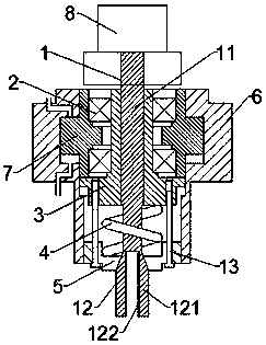
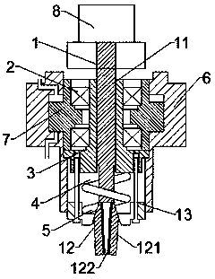
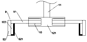
[0018] Such as Figure 1-3 As shown, a circuit board processing and clamping device is installed at the end of the mechanical arm for clamping the circuit board, including a chuck 1, a bearing 2, a push sleeve 3, a spring 4, a locking plate 5, and a first cylinder 6 And the piston 7 arranged in the first cylinder 6, the chuck 1 includes a solid rotating rod 11 at the upper end and a clamping part 12 connected to the lower end of the rotating rod 11 and composed of two clamping plates 121, the clamping plates 121 are parallel to each other Set, each clamping plate 121 can be elastically deformed along the relative direction, and the outer side of the end connected with...


PUM


Abstract

The invention provides a clamping device for circuit board processing. The clamping device is mounted at the end part of a mechanical arm, is used for clamping a circuit board, and comprises a clamping head, a bearing, a pushing sleeve, a spring, a locking plate, a first cylinder and a piston, wherein the clamping head comprises a rotating rod as well as a clamping part connected to the lower end of the rotating rod and consisting of two clamping plates; each clamping plate can be elastically deformed in the opposite direction, and the outer side of the end, connected with the rotating rod, of each clamping plate is a conical surface; a motor is connected to the top end of the clamping head; a through hole matched with the rotating rod is formed in the pushing sleeve, and the pushing sleeve is rotatably supported inside the piston; an inner conical hole matched with the outer conical surfaces of the clamping plates is formed in the locking plate, and the locking plate is slidably arranged below the inner cavity of the first cylinder; the rotating rod of the clamping head is inserted into the through hole in the pushing sleeve; the clamping part is placed inside the inner conical hole in the locking plate; the spring sleeves the clamping head, and the two ends of the spring are pressed against the pushing sleeve and the locking plate respectively. The clamping device has the advantages that the clamping device can flexibly clamp the circuit board, can maintain relatively high stability so as to prevent falling, and improves the processing accuracy.

Description

technical field [0001] The invention relates to the technical field of circuit board clamping, in particular to a circuit board processing and clamping device. Background technique [0002] The circuit board makes the circuit miniaturized and intuitive, and plays an important role in mass production of fixed circuits and optimizing the layout of electrical appliances. Circuit boards can be called printed circuit boards or printed circuit boards and rigid-flex boards. During the processing and molding of circuit boards, it is necessary to package electronic components, overhaul and complete performance testing in multiple processes. [0003] At present, the clamping mechanism used to clamp the circuit board for processing and maintenance in the prior art is not reasonable enough, the circuit board cannot be clamped quickly and stably, and the operation is not convenient enough. When clamping the circuit board, due to the clamping structure Working for a long time, it is dif...

Claims


Application Information

Patent Timeline
IPC IPC(8): H05K3/00
CPCH05K3/00H05K2203/15
Inventor 王庆文
Owner 南京万云信息技术有限公司
Learn More