A power supply for LED lamps with timing power reduction
What is Al technical title?
Al technical title is built by PatSnap Al team. It summarizes the technical point description of the patent document.
A LED lamp power reduction technology, applied in the field of timing power reduction LED lamp power supply, can solve the problems of increasing production costs, increasing energy consumption, increasing environmental pollution, etc., to facilitate installation and disassembly, reduce energy loss, The effect of reducing the cost of use
Active Publication Date: 2019-01-25
中山市恒能电子科技有限公司
View PDF10 Cites 0 Cited by
Summary
Abstract
Description
Claims
Application Information
AI Technical Summary
This helps you quickly interpret patents by identifying the three key elements:
Problems solved by technology
Method used
Benefits of technology
Problems solved by technology
[0003] In the prior art, there is no short-circuit protection mechanism installed in the traditional traditional LED lamp power supply, resulting in that the circuit cannot be automatically shut down and cannot automatically alarm when the circuit is short-circuited, which will easily lead to damage to the main components of the power supply, increase production costs, and easily Cause a fire, the traditional LED lamp power supply does not have a timing power reduction mechanism, resulting in the LED lamp usually using a constant power to work, resulting in the inability to intelligently regulate the LED lamp power supply, increasing energy loss, wasting non-renewable energy, and increasing pollution to the environment
Method used
Image
Click on the blue label to locate the original text in one second.
Reading with bidirectional positioning of images and text.
Examples
specific Embodiment approach
[0027]Specific implementation method: when the main body of the power supply is energized and running, the short-circuit protection mechanism works, the live wire L transmits the current to the fuse F1, and then the fuse F1 transmits the current to the rectifier transformer L1, and then the rectifier transformer L1 transmits the current to the rectifier transformer L2 and Capacitor CX1, then the rectifier transformer L2 sends the current to the rectifier U, and then the rectifier U sends the current to the main body of the power supply. When the main body of the power supply is short-circuited, the rectifier U receives the short-circuit signal and sends an instruction, the capacitor CX1 and capacitor CX2 are disconnected, and the fuse F1 stop working, the design realizes the short circuit protection of the main body of the power supply.
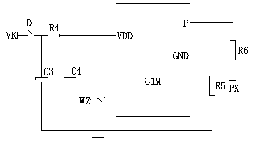
[0028] When the LED lamp L5 works for four hours, the PWM regulator U1M works and sends an instruction, the value of the resistor R6 increase...
PUM
Abstract
The present invention provides a power supply for LED lights with timing power reduction, which includes fuse F1, rectifier transformer L1, capacitor CX1, filter U, rectifier transformer L3, sliding resistor VR2, diode D, resistor R4, filter capacitor C3, and voltage regulator diode WZ , PWM regulator U1M and resistor R6, the right end of fuse F1 is connected to rectifier transformer L1, the right end of rectifier transformer L1 is connected to capacitor CX1, the right end of capacitor CX1 is installed with filter U, the right end of filter U is connected to rectifier transformer L3, and the right end of rectifier transformer L3 is connected to sliding resistor VR2, this design realizes the protection of the main body of the power supply, the right end of the diode D is respectively connected to the resistor R4 and the filter capacitor C3, the right end of the resistor R4 is respectively connected to the Zener diode WZ and the PWM regulator U1M, and the right end of the PWM regulator U1M is connected to the resistor R6. The output power of the LED lamp L5 can be adjusted, it is easy to operate, it can protect the circuit, it can be intelligently adjusted, it is easy to disassemble, it has good stability and high reliability.
Description
technical field [0001] The invention is a power supply for LED lamps with timing power reduction, which belongs to the field of LED lamp power supply equipment. Background technique [0002] LED power supply is a kind of power supply. It is a device that provides power to electronic equipment, also known as a power supply. It is deployed as a different power input on the device connected to an independent circuit device with two or three power inputs. Dry batteries, etc. are also called power supplies; devices that convert alternating current into direct current through transformers and rectifiers are called rectified power supplies. [0003] In the prior art, there is no short-circuit protection mechanism installed in the traditional traditional LED lamp power supply, resulting in that the circuit cannot be automatically shut down and cannot automatically alarm when the circuit is short-circuited, which will easily lead to damage to the main components of the power supply, ...
Claims
Application Information
Patent Timeline
Application Date:The date an application was filed.
Publication Date:The date a patent or application was officially published.
First Publication Date:The earliest publication date of a patent with the same application number.
Issue Date:Publication date of the patent grant document.
PCT Entry Date:The Entry date of PCT National Phase.
Estimated Expiry Date:The statutory expiry date of a patent right according to the Patent Law, and it is the longest term of protection that the patent right can achieve without the termination of the patent right due to other reasons(Term extension factor has been taken into account ).
Invalid Date:Actual expiry date is based on effective date or publication date of legal transaction data of invalid patent.