
Liquid crystal display device with switchable viewing angle

A liquid crystal display device and viewing angle technology, which is applied in instruments, nonlinear optics, optics, etc., can solve the problems affecting the contrast and transmittance of liquid crystal display devices, and achieves the improvement of transmittance and contrast, narrow viewing angle, and wide viewing angle. Effect

Active Publication Date: 2019-04-05
KUSN INFOVISION OPTOELECTRONICS
View PDF4 Cites 0 Cited by
  • Summary
  • Abstract
  • Description
  • Claims
  • Application Information

AI Technical Summary

Problems solved by technology

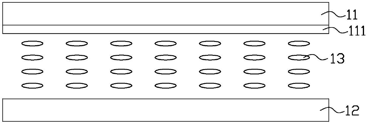
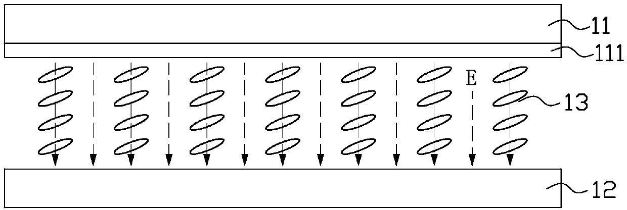
[0005] However, in this way, in the wide viewing angle mode, since the viewing angle control electrode does not provide voltage or the potential is very small, a large gap will be generated between the pixel electrode strip of the pixel electrode (not shown) and the viewing angle control electrode during wide viewing angle display. Potential difference, there is a strong vertical electric field between the pixel electrode strips and the viewing angle control electrode, which makes the liquid crystal molecules corresponding to each pixel electrode strip deflect at a large angle, which affects the contrast and transmittance of the liquid crystal display device under wide viewing angle display

Method used


Image

  • Liquid crystal display device with switchable viewing angle
  • Liquid crystal display device with switchable viewing angle
  • Liquid crystal display device with switchable viewing angle

Examples


no. 1 example

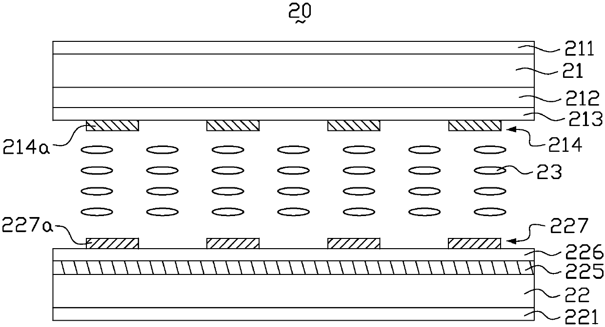
[0032] image 3 It is a schematic structural diagram of a liquid crystal display device at a wide viewing angle in the first embodiment of the present invention, Figure 4 for image 3 Schematic diagram of the liquid crystal display device in the narrow viewing angle, please refer to image 3 and Figure 4 , the liquid crystal display device includes a display panel 20 , and the display panel 20 includes a first substrate 21 , a second substrate 22 opposite to the first substrate 21 , and a liquid crystal layer 23 between the first substrate 21 and the second substrate 22 .

[0033] Generally, when the user views the screen of the liquid crystal display device from different viewing angles, the brightness of the image will decrease as the viewing angle increases. In a traditional Twisted Nematic (TN) liquid crystal display device, the common electrode and the pixel electrode are respectively formed on two different upper and lower substrates, and the liquid crystal molecule...

no. 2 example

[0062] Figure 11 It is a schematic structural diagram of a liquid crystal display device at a narrow viewing angle in the second embodiment of the present invention, Figure 12 for Figure 11 Schematic diagram of the structure of a liquid crystal display device at a wide viewing angle, please refer to Figure 11 and Figure 12 The main difference between this embodiment and the first embodiment above is that the liquid crystal layer 23 in this embodiment uses negative liquid crystal molecules. In the initial state (i.e. when no voltage is applied to the display panel 20), the negative liquid crystal molecules in the liquid crystal layer 23 have a relatively large initial pretilt angle relative to the substrates 21, 22, that is, the negative liquid crystal molecules have relatively large initial pretilt angles relative to the substrates 21, 22, 22 in a tilted posture (such as Figure 11 ). Under the action of the electric field formed by the applied voltage, the long axes...


PUM


Abstract

The invention discloses a liquid crystal display device capable of switching a visual angle. The liquid crystal display device comprises a display panel, wherein the display panel comprises a first substrate, a second substrate opposite to the first substrate, and a liquid crystal layer located between the first substrate and the second substrate; a visual angle control electrode and suspending electrodes are arranged on the first substrate in a mutual insulation manner; a public electrode and pixel electrodes are arranged on the second substrate in the mutual insulation manner; the pixel electrodes are arranged in each subpixel and comprise a plurality of spaced pixel electrode bars; the suspending electrodes are arranged in each subpixel and comprise a plurality of spaced suspending electrode bars; all the suspending electrodes and all the pixel electrodes are arranged in an up-and-down correspondence manner; the suspending electrodes are in suspending state; the visual angle control electrode is used for applying a voltage signal for controlling visual angle switching.

Description

technical field [0001] The invention relates to the technical field of liquid crystal display, in particular to a liquid crystal display device with a switchable viewing angle. Background technique [0002] Liquid crystal display (liquid crystal display, LCD) has the advantages of good image quality, small size, light weight, low driving voltage, low power consumption, no radiation and relatively low manufacturing cost, and occupies a dominant position in the field of flat panel display. [0003] Currently, liquid crystal display devices are gradually developing toward wide viewing angles. For example, liquid crystal display devices using in-plane switching (IPS) or fringe field switching (FFS) modes can achieve wider viewing angles. The wide viewing angle design allows users to see a complete and undistorted picture from all directions. However, in today's society, people pay more and more attention to protecting their privacy, and there are many things that they don't lik...

Claims


Application Information

Patent Timeline
Patent Type & Authority Patents(China)
IPC IPC(8): G02F1/13G02F1/1343
CPCG02F1/1323G02F1/1343
Inventor 姜丽梅苏日嘎拉图王新刚
Owner KUSN INFOVISION OPTOELECTRONICS
Learn More