
Sky-wave over-the-horizon radar target and ionized layer parameter joint estimation method

A technology of over-the-horizon radar and target parameters, which is applied in the field of radar, and can solve problems such as ignoring detection equipment errors, interference, and high input signal-to-noise ratio

Inactive Publication Date: 2017-02-22
UNIV OF ELECTRONICS SCI & TECH OF CHINA
View PDF4 Cites 3 Cited by
  • Summary
  • Abstract
  • Description
  • Claims
  • Application Information

AI Technical Summary

Problems solved by technology

The ionospheric parameters are obtained by the inversion of the ionospheric detection equipment, which has a large measurement error. In similar algorithms, the ionospheric parameters are regarded as unbiased information, ignoring the error of the detection equipment, and the estimated target parameters are all not precise enough
[0003] The existing sky-wave radar maneuvering target parameter estimation algorithms mainly fall into two categories: the first is the maneuvering target detection method based on time-frequency analysis, such as the adaptive wavelet transform algorithm (Wang G, Xia X G, Root B T, et al. Movingtarget detection in over-the-horizon radar using adaptive chirplet transform[J].Radio Science,2002,38(4):77-84.) and Wigner-Ville decomposition method (Frazer G J,AndersonS J.Wigner-Ville analysis of HF radar measurement of an accelerating target[C]International Symposium on Signal Processing and ITS Applications.1999:317-320vol.1.), but when there are multiple maneuvering targets, this type of method will be interfered by the cross term
The second category is the maneuvering target detection algorithm based on polynomial phase modeling, such as the maneuvering target compensation method based on the high-order ambiguity function (HAF) (LuK, Liu X. Enhanced visibility of maneuvering targets for high-frequency over-the-horizon radar [J].IEEE Transactions on Antennas&Propagation,2005,53(1):404-411.), this method solves the coefficients of each order of the polynomial through the high-order fuzzy function to estimate the parameters of the maneuvering target, which has the advantage of low calculation amount, but this method The method requires a high input signal-to-noise ratio when solving the high-order coefficients of polynomials, and there is an obvious error accumulation effect
The other is a maneuvering target detection algorithm based on Cubic Phase Function (CPF) (O'Shea P.A new technique for instantaneous frequency rate estimation [J]. IEEE Signal Processing Letters, 2002, 9(8): 251-252 .), the algorithm avoids the multiple use of nonlinear transformation and reduces the SNR loss, but the estimation accuracy is not high
[0004] In engineering practice, the measurement error of ionospheric detection equipment seriously affects the target parameter estimation accuracy of sky-wave over-the-horizon radar, and all current maneuvering target parameter estimation algorithms do not consider the influence of ionospheric detection equipment error

Method used


Image

  • Sky-wave over-the-horizon radar target and ionized layer parameter joint estimation method
  • Sky-wave over-the-horizon radar target and ionized layer parameter joint estimation method
  • Sky-wave over-the-horizon radar target and ionized layer parameter joint estimation method

Examples


Embodiment 1

[0065] Embodiment 1: Performance analysis combined with classic maximum likelihood algorithm:

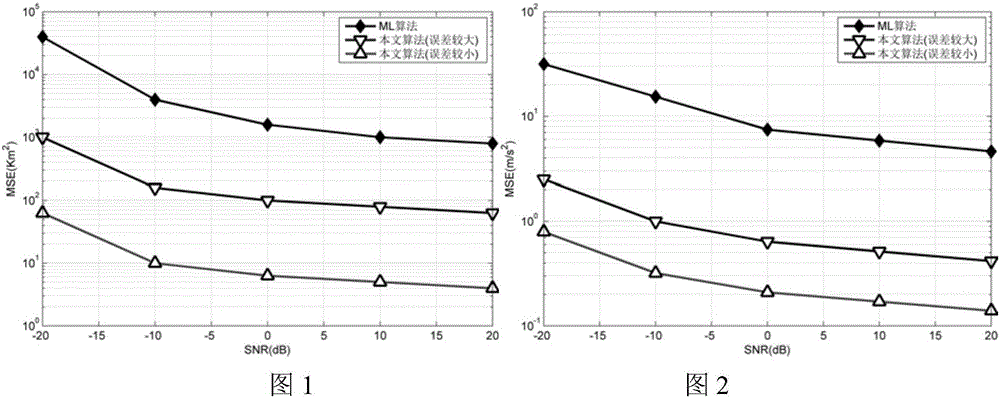
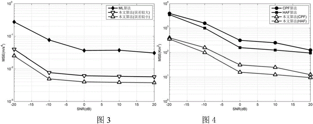
[0066] Fig. 1 is the mean square error (MSE) curve of the target distance estimated by the method of the present invention (the algorithm in the figure, the same below) and the maximum likelihood (ML) algorithm respectively. Figure 2 and Figure 3 are the MSE curves of the estimated target velocity and acceleration under the same conditions. It can be seen from the figure that as the SNR increases, the MSE curve gradually decreases, and the estimation error gradually decreases. The curve of the method proposed in the present invention is significantly lower than the classic maximum likelihood method, which shows that the method is always better than the maximum likelihood method. In the case of a small ionospheric detection equipment error, the proposed method has a smaller estimation error, but because the error information of the ionosphere is not used, the parameter error of the ion...

Embodiment 2

[0067] Embodiment 2: Performance analysis combined with other target estimation algorithms

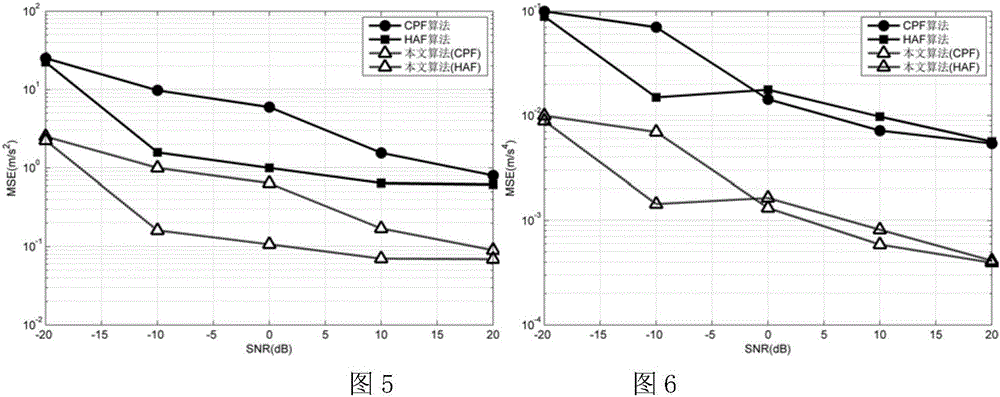
[0068] Figure 4 is the HAF and CPF methods, and the mean square error (MSE) curve of the estimated target distance improved by the method of the present invention. Figures 5 and 6 are the MSE curves of the estimated target speed and acceleration under the same conditions. It can be seen from the figure that as the SNR increases, the estimation errors of all algorithms decrease. In most cases, the CPF algorithm is better than the HAF algorithm, which is caused by the algorithm's different sensitivity to SNR. In addition, it can be found that the MSE curve applied with the method of the present invention is significantly lower than the HAF and CPF algorithms, and is equally spaced compared to the original curve, which is consistent with the theory and proves that the method proposed by the present invention is existing Further update and improvement of the algorithm can improve the estima...


PUM


Abstract

The invention discloses a sky-wave over-the-horizon radar target and ionized layer parameter joint estimation method, which belongs to the field of radar technologies. According to the invention, a parameter to be estimated is set as a target and ionized layer joint parameter; an analytical model is used to transform the error of an ionized layer detection device into a target parameter estimation error; and the estimated parameter is corrected to realize ionized layer and target parameter joint estimation. The problem that joint ionized layer parameter error estimation cannot be carried out by the existing estimation method is solved. The ionized layer error information is effectively utilized. The estimation accuracy is improved.

Description

Technical field [0001] The invention belongs to the field of radar technology, and specifically relates to an algorithm for joint estimation of target parameters of sky-wave over-the-horizon radar using ionospheric information. Background technique [0002] OTHR (Over-the-horizon radar) uses 3-30MHz high-frequency electromagnetic waves to propagate from top to bottom through ionospheric reflection. It can achieve large-area, ultra-long-distance target detection, which is important Tactical and strategic value. In the current OTHR research, the estimation of target parameters is the fundamental purpose of OTHR engineering application, so accurate estimation of target parameters is of great significance. Due to the special working method of OTHR, the study of the ionosphere is very important. The ionospheric parameters are obtained by inversion of the ionospheric detection equipment. The equipment has large measurement errors. In similar algorithms, the ionospheric parameters are...

Claims


Application Information

Patent Timeline
IPC IPC(8): G01S7/41
CPCG01S7/41
Inventor 胡进峰薛长飘
Owner UNIV OF ELECTRONICS SCI & TECH OF CHINA
Learn More