Fume temperature uniform distribution device of rotary air preheater outlet flue
An air preheater and outlet flue technology, applied in lighting and heating equipment, combustion methods, indirect carbon dioxide emission reduction, etc., can solve problems such as deviation, affecting the performance of electrostatic precipitators, affecting dust removal effects, etc. Benefit and economic benefits, improve the performance of flue gas treatment, improve the effect of uneven flue gas temperature
- Summary
- Abstract
- Description
- Claims
- Application Information
AI Technical Summary
Problems solved by technology
Method used
Image
Examples
Embodiment 1
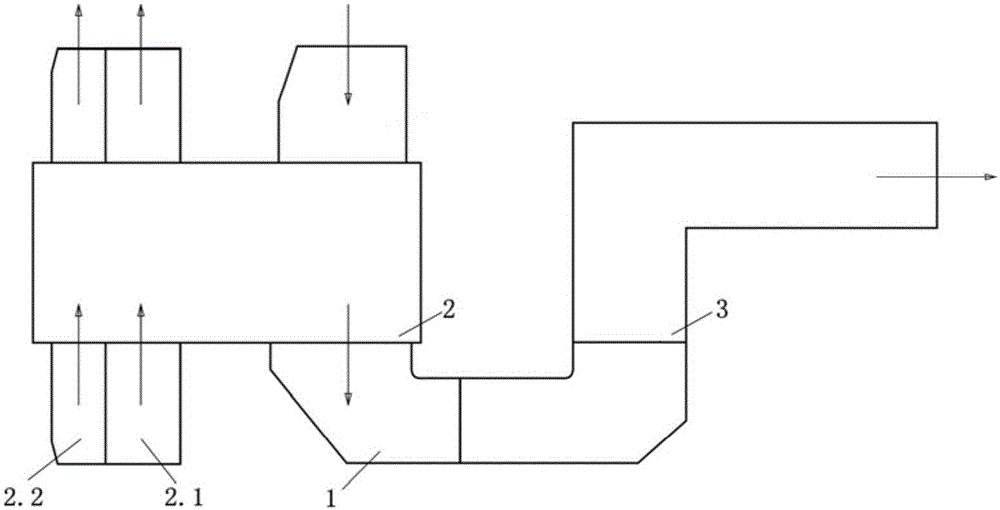
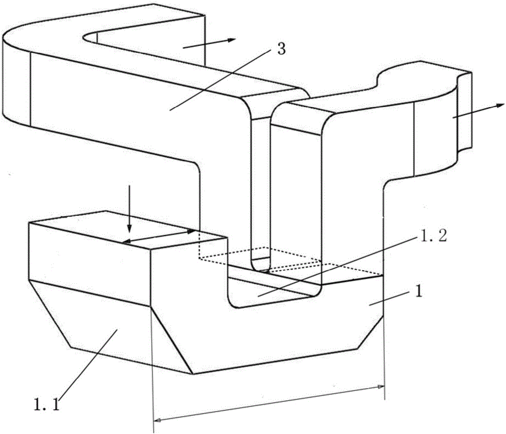
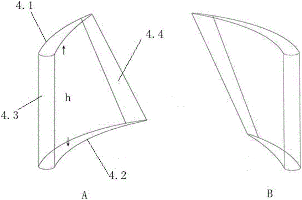
[0035] like Figure 2-6 As shown, a device for uniform flue gas temperature distribution at the outlet of a rotary air preheater, the device includes a U-shaped flue 1, one end of the U-shaped flue 1 is connected to the outlet 2 of the rotary air preheater, and the other end Two independent dust collector connecting pipes 3 are arranged side by side on the flue opening. The pipe of the U-shaped flue 1 is a rectangular passage, and the U-shaped flue 1 includes an outer wall surface 1.1 and an inner wall surface 1.2 parallel to each other, and the outer wall surface 1.1 and the inner wall surface. A plurality of rows of airfoil blades 4 are arranged on the inner surface of the wall 1.2 along the direction of smoke discharge, and the deflection direction of the airfoil blades 4 on the outer wall 1.1 is opposite to that of the airfoil blades 4 on the inner wall 1.2. The airfoil blades 4 on the outer wall surface 1.1 and the airfoil blades 4 on the inner wall surface 1.2 only overl...
Embodiment 2
[0050] like figure 2 , 3 , Shown in 4, 5 and 7: the device of the present embodiment is basically the same as embodiment 1, the difference is:
[0051] The airfoil blades 4 on the outer wall surface 1.1 and the airfoil blades 4 on the inner wall surface 1.2 are arranged without any overlap in the flue, that is, the airfoil blades 4 on the inner wall surface 1.2 are located on the adjacent airfoil blades on the outer wall surface 1.1 4. A certain area between the channels formed is a full staggered arrangement.
Embodiment 3
[0053] like figure 2 , 3 , Shown in 4, 5 and 6: the device of the present embodiment is basically the same as embodiment 1, the difference is:
[0054] The arrangement in which the airfoil blades 4 on the outer wall surface 1.1 and the airfoil blades 4 on the inner wall surface 1.2 completely overlap in the flue is a fully matching arrangement.
PUM
| Property | Measurement | Unit |
|---|---|---|
| Diameter | aaaaa | aaaaa |
Abstract
Description
Claims
Application Information
 - R&D Engineer
- R&D Manager
- IP Professional
- Industry Leading Data Capabilities
- Powerful AI technology
- Patent DNA Extraction
Browse by: Latest US Patents, China's latest patents, Technical Efficacy Thesaurus, Application Domain, Technology Topic, Popular Technical Reports.
© 2024 PatSnap. All rights reserved.Legal|Privacy policy|Modern Slavery Act Transparency Statement|Sitemap|About US| Contact US: help@patsnap.com


